Hi
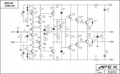
I want to ask if I can replace V101,103, 113 with 2N5210. Also 2SA1381C, 2SC3503C with MJE 253, MJE 243, I just have plenty of these Motorola transistors.
Thanks,
Saksit
I want to ask if I can replace V101,103, 113 with 2N5210. Also 2SA1381C, 2SC3503C with MJE 253, MJE 243, I just have plenty of these Motorola transistors.
Thanks,
Saksit
Hi, All.
Can someone tell me is there any substitute for MR854?
Maybe some FR, BY, 1N, MUR, MBR...
Can someone tell me is there any substitute for MR854?
Maybe some FR, BY, 1N, MUR, MBR...
Hi Andrew, Can you indicate the site where you find this Pcb?Tone control from the internet works well with AX14
warm regards
Andrew
Thanks
Can't see anything attached with your postHere for home etching pcbs
Hi all!
I have a question about the APEX P30ZF preamplifier. Has anyone measured THD? What were the results?
What regulates a 1k ohm trimmer? In my case, I do not see any changes from the adjustment.
Thank you.
I have a question about the APEX P30ZF preamplifier. Has anyone measured THD? What were the results?
What regulates a 1k ohm trimmer? In my case, I do not see any changes from the adjustment.
Thank you.
referring to this layout and sch , R26 and Led are indeed present.
A couple of questions about the small single board FH9,
- the single board version schematic has C5 listed as 1000uf, but the parts list shows it as 220uf, as does the double board version schematic, so I am going to go with, the single board schematic is wrong and C5 should be 220uf.
- the single board schematic version has R5 at 22K which is not on the parts list, but there is a R26 on the parts list at 22K that is not on the single version schematic. I am going to go with R26 on the parts should be R5.
- the board parts list shows an LED and test points that should be installed, but these are not present on the single board PCB, just the double board version.
Anyone on here made the single board version of Prasis APEX XRK971 MOD FH9 amplifier?

Here is nice PCB Design For APEX A-Class PSU that uses single layer PCB, have CRC snubbler to suppress toroidal ringing, full bridge rectifier and CRC filtering for smooting and PSRR on 50Hz to be minimal, using A-Class from APEX circuit to provide low noise, high PSRR, low impendance out and routed for audio circuit.
NOTE: Rename BRD file extension to LAY6 and open in Sprint-Layout, because diyAudio forum does not allow uploading LAY6 files!
Enyoy!


NOTE: Rename BRD file extension to LAY6 and open in Sprint-Layout, because diyAudio forum does not allow uploading LAY6 files!
Enyoy!
Attachments
And Here is build of this nice Shunt From APEX from other member and he is very impressed with sound quality from this shunt, thanks APEX!


What is the maximum current?Here is nice PCB Design For APEX A-Class PSU that uses single layer PCB, have CRC snubbler to suppress toroidal ringing, full bridge rectifier and CRC filtering for smooting and PSRR on 50Hz to be minimal, using A-Class from APEX circuit to provide low noise, high PSRR, low impendance out and routed for audio circuit.
NOTE: Rename BRD file extension to LAY6 and open in Sprint-Layout, because diyAudio forum does not allow uploading LAY6 files!
Enyoy!
View attachment 1099620
View attachment 1099621
Thanks, I'm thinking of using it to feed a pre, a two-band equalizer and a cross with only one source.Maximum current is 0,65V/22R=cca 29mA...if you need large current for load use 10R/2W resistor then max current is 0,65V/10R=65mA....for large currents use serial psu not this shunt as it dissipates a lot of heat if used on 100mA or more load current.
How did you assemble such a scheme?The Apex AX-17 amplifier circuit does not indicate the power of the resistors.
What power resistors to use in the Apex AX-17 amplifier when powered +- 35-40 VDC ???
For a gain of 33dB, a voltage of +/-35 ... 40 volts is not enough for modern signal sources.
A more reasonable ratio of R15C6 is when R15 = 56 ohm C6 = 1000uF, because the feedback input is low impedance,
Also with R15 = 56 ohm C6 = 1000uF the gain will drop to a logical 25.4dB.
the second point is thermal stability, in principle, a simple Bailey multiplier will not keep three PN transitions of the Lokanti output stage from heating.
the operating modes of the driver stage are very weak, the linearity is low, it will not work to get low distortion without selecting active elements for amplification ....
The power of the resistors is sufficient 0.25 watts, because weak current modes ...
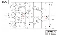
the simplest thing that can be offered is such a correction modification.
It is also necessary to select resistors R18 or R19 to minimize the value of the DC voltage at the output of the circuit.(of necessity)
P.S. The reason for the revision of the modes is that the transient responses have spikes due to the low-current modes of the drivers operating on the corrective capacitance. Increasing the depth of negative feedback (changing the values of R15R16 C6) partially solves the problem with the transient response.
Attachments
Last edited:
- Home
- Amplifiers
- Solid State
- 100W Ultimate Fidelity Amplifier