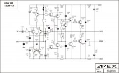
I made this amplifier for test my home DIY speakers (two way TL).
D4 on component layout wrong polarity, in post #253 is corect componenet layout.
D4 on component layout wrong polarity, in post #253 is corect componenet layout.
Attachments
Last edited:

Hi Mile, at least i think that's right 🙂
Much as i love your thread on the class H amplifier (& i won't forget how you have possibly helped me create something of improved efficiency 😉) you need to bias that thing into class A & then you'll get even more fidelity.
You'll need to parallel output transistors & use huge heatsinks but i feel sure that class A biasing will show you the "ultimate fidelity". Admittedly a well biased class B is good, going OTT is the final hurdle & a rather fascinating transformation...
Bests to you chap & thanks for your posts on lots of interesting stuff, i for one seriously appreciate it 🙂 Oh, i'm sure something will come of your input one day in the not too distant future 😉
Bests, Mark.
Amplifier is made to be better than most comercial home amps, and give me expect sound of my speakers in usual home audio sistem.
Thanks MarkHi Mile, at least i think that's right 🙂
Much as i love your thread on the class H amplifier (& i won't forget how you have possibly helped me create something of improved efficiency 😉) you need to bias that thing into class A & then you'll get even more fidelity.
You'll need to parallel output transistors & use huge heatsinks but i feel sure that class A biasing will show you the "ultimate fidelity". Admittedly a well biased class B is good, going OTT is the final hurdle & a rather fascinating transformation...
Bests to you chap & thanks for your posts on lots of interesting stuff, i for one seriously appreciate it 🙂 Oh, i'm sure something will come of your input one day in the not too distant future 😉
Bests, Mark.
Can we have the PCB layout to etch our own boards? I'm looking for new amplifier to try.
Apex do you have something similar with this one but with 2 pairs of output transistors? That is what I'm looking for but is hard to find. Was looking at Bora's Techno amplifier but I don't have enough info to make my own...yet...who knows.
Apex do you have something similar with this one but with 2 pairs of output transistors? That is what I'm looking for but is hard to find. Was looking at Bora's Techno amplifier but I don't have enough info to make my own...yet...who knows.
Yeah he likes to post schematics with mistakes 😛
He will post the correct schematics after a while, I hope.
Can u name some mistakes?
He will post the correct schematics after a while, I hope.
Can u name some mistakes?
R8 and R2 values are reversed..
R8 must be 560R and R2 22K...
C7 value ,is plain wrong , and should be much lower,
something between 3.3 and 18pF..
As i pointed it with many of his designs, R5 and C3
must be removed as they create a hard rail sticking when
the amp is overloaded.
There s better means to achive stability.....
R8 must be 560R and R2 22K...
C7 value ,is plain wrong , and should be much lower,
something between 3.3 and 18pF..
As i pointed it with many of his designs, R5 and C3
must be removed as they create a hard rail sticking when
the amp is overloaded.
There s better means to achive stability.....
Thumbs down for this design so far
I'm not much of an expert but I agree about C7, can't comment about the rest.
Thank you for the feedback.
I'm not much of an expert but I agree about C7, can't comment about the rest.
Thank you for the feedback.
Thanks Wahab,R8 and R2 values are reversed..
R8 must be 560R and R2 22K...
C7 value ,is plain wrong , and should be much lower,
something between 3.3 and 18pF..
As i pointed it with many of his designs, R5 and C3
must be removed as they create a hard rail sticking when
the amp is overloaded.
There s better means to achive stability.....
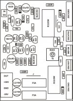
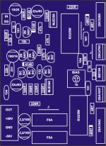
R2 and R8 values are reversed on schematics, on PCB is OK,
C7 can be lower 47pF is minimum
C9,C10 can be lower 22pF is minimum
Rest is OK
Regards Mile
Last edited:
C7 330pF is maximum value for stability, but can be lower after tested.I'm not much of an expert but I agree about C7, can't comment about the rest.
Thank you for the feedback.
C7 330pF is maximum value for stability, but can be lower after tested.
At 330pF, it will severly affect the bandwith of the amp,
having influence below 20khz.
At 47pF , although i find the value still high, the bandwith
will be large enough, over 100khz...
Anyway, i appreciate that you re proposing many ideas
to help people make some builds, particularly your
well done PCBs.
regards,
Wahab do you know Marfy's Law in electronic: Amplifiers always oscilate and Oscilators always amplify.
Regards Mile
Regards Mile
Last edited:
Wahab do you know Marfy's Low in electronic: Amplifiers always oscilate and Oscilators always amplify.
Regards Mile
Lol...That s a good one, Mile..
Perhaps that to make a good amplifier, we should start
designing a good oscillator...
regards
wahab
You have on my other thread PCB layout with 2 pairs of output transistors irfp240/irfp9240 mosfets in "DC servo mosfet amplifier" and bdw83d/bdw84d darlingtons in "Amplifier motherboard". I sugest you DC servo mosfet amp. There is PCB for PSU and protect.Can we have the PCB layout to etch our own boards? I'm looking for new amplifier to try.
Apex do you have something similar with this one but with 2 pairs of output transistors? That is what I'm looking for but is hard to find. Was looking at Bora's Techno amplifier but I don't have enough info to make my own...yet...who knows.
Regards Mile
I suppose if one is locked into the idea there can only be one plus and one minus supply this is a good design- now if you leave that idea behind then... a lot of improvement can be made and a lot of those slow current sources can be replaced by fast resistors. Every current source slows the propagation through the amp.
- Home
- Amplifiers
- Solid State
- 100W Ultimate Fidelity Amplifier