Is this correct?
Reverced all TO92 transistors
All 2n5551 and mpsa92
Reverced all TO92 transistors
All 2n5551 and mpsa92
An externally hosted image should be here but it was not working when we last tested it.
Is this correct?
Reverced all TO92 transistors
All 2n5551 and mpsa92
An externally hosted image should be here but it was not working when we last tested it.
No MPSA92 polarity is OK
hello sit that is actually a change I did to the file myself from mister Willy I do have the files gerbers and Sprint file if want too I'll attached them here 🙂
Attachments
Ok
Why board not worked?
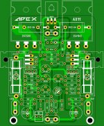
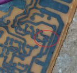
There is some mistake on your pcb... HX11 work.
Attachments

This picture do not have good quality.There is some mistake on your pcb... HX11 work.
What is the mistake?
This picture do not have good quality.
What is the mistake?
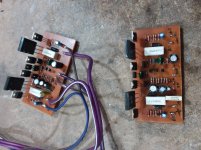
Please, Hadi, post some pictures of the bottom side of the PCB. 🙄
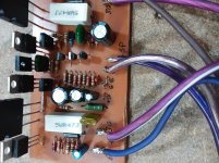
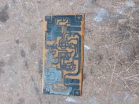
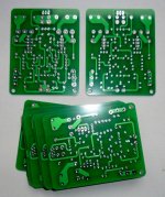
On the PCB with the wires (first image) the MPSA92 is reversed and all the 2N5551 are correct.
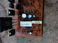
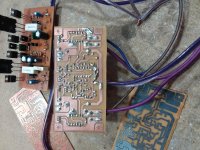
On the other PCB (second image) The MPSA92 is correct but all the 2n5551 are inverted.
Are you sure that the two diodes above the capacitor of 47uF are indeed 1N4148 because I find them big!
On the other PCB (second image) The MPSA92 is correct but all the 2n5551 are inverted.
Are you sure that the two diodes above the capacitor of 47uF are indeed 1N4148 because I find them big!
Please, Hadi, post some pictures of the bottom side of the PCB. 🙄
it is this pcb
Attachments
On the PCB with the wires (first image) the MPSA92 is reversed and all the 2N5551 are correct.
On the other PCB (second image) The MPSA92 is correct but all the 2n5551 are inverted.
Are you sure that the two diodes above the capacitor of 47uF are indeed 1N4148 because I find them big!
1. i test it in different condithion
2. i assembled mpsa92 like the pcb and 2n5551 in reversed the pcb file and all is correct.
3. yes. that is 4148
i do not undrestand what is the problem. 2sc5200 and irf540 and irf9540 after 1 second is very hot wen i conected power to the board.
No, post photography bottom side of your PCB!it is this pcb
Attachments
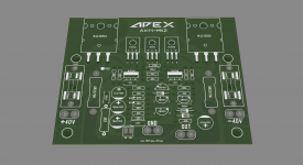
Hello everyoneHello everyone
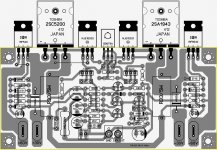
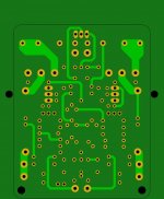
For fun I drew a layout of the AX11 amplifier based on the miniamp with some small modifications to facilitate setting up on the heatsink.
I checked the connections and there is no error but I do not know yet if I will make this amplifier.
If the gerber or .lay6 files are of interest to someone, I will make them available.
🙂
Finally I will make this amplifier. I received the PCBs but I forgot to give a color for the Silkscreen. 😀
Regard's
Attachments

Check this too pleae
What is that?
Attachments

What is that?
It is input
If conect to groud we dont have out put sound
Why c5200 is hot?
This is the probleme
- Home
- Amplifiers
- Solid State
- 100W Ultimate Fidelity Amplifier