I will have to go back and read though again. I used screenprint from post 3576. I see now that there are new versions. I used TL072. All TO92 are what are called out in the screen print. Without a matching schematic, trouble shooting is very difficult.
Thanks, Terry
posts 3583, 3587.
.
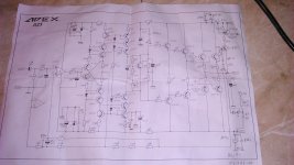
schematic is APEX A23. now i am typing from mobile and don't have schematic in it.
I can't get it to full rails because the bias is too high. I will investigate. Further tomorrow.Can you post voltage measurements on IC and transistors pins?
This board does not match A 2 3 schematic. Many part changes and added parts.schematic is APEX A23
Hi Apex.
In AX-20, can we use 2Nseries instead of BC547 and BC557? or any other substitute that can find in SMD package?
In AX-20, can we use 2Nseries instead of BC547 and BC557? or any other substitute that can find in SMD package?
Hi Apex.
In AX-20, can we use 2Nseries instead of BC547 and BC557? or any other substitute that can find in SMD package?
Use BC847 and BC857
I can't get it to full rails because the bias is too high. I will investigate. Further tomorrow.
This board does not match A 2 3 schematic. Many part changes and added parts.
i am sorry but i must conclude that you never actually compared APEX A23 schematics with a pcb that i have drawn - because if you had,you would not say something like that.
down here is a schematics of A23 that we all were given.
the protection (compatible to APEX-Zack NE555 speaker-protection) and Clip-Indication part is what i added to a pcb (i said that earlier!) and on this paper it is drawn by hand. i also added a few capacitors as you can see (seven of 100nF and two of 1000uF),and that as all we can see did not in any way changed APEX A23 basic schematics.
after all of what i did up till now (two kind of a pcb and all possible documents about them i could provide (including top side layout(s)),redrawn schematics with all i did aditional) i can´t help you any more,because i don´t know that much,providing help by getting some voltage mesurnaments is far beyond my capabilities. all i can do is to advice you to check all the copper lines if they are as they should be,not connecting with near close lines,if all the transistors and resistors are on their places. that is the most common mistake that i do,and i did them when compleeting second A23 pcb - switched places to BC550 and BC560 in input and one copper line between C and E ov 2SC4793. fixed it and it works.
one more thing,the lines across the parts on schematics were drawn when i was doing part list...
Attachments
Last edited:
Still,
if you printed a paper version of a top side screen print and glue this to the top side, you could "label" all the component locations.
This would help avoid assembly errors.
It would help massively during debugging, since all components would be labeled, by component number and value.
Did you add in any "test points" ? I don't see any loops for clipping on test probes.
couldn´t agree more: top side printed on a pcb helps a lot during assembling an amplifier. it kind look´s good when it is applied to a pcb but more important is the fact that is much easier to assemble it.
the fact is that both pcb´s are checked and working (at least in my and Djera´s case),so there is a mistake on your pcb just waiting to be found...
the fact is that both pcb´s are checked and working (at least in my and Djera´s case),so there is a mistake on your pcb just waiting to be found...
I can't get it to full rails because the bias is too high. I will investigate. Further tomorrow.
This board does not match A 2 3 schematic. Many part changes and added parts.
Use 1k trimpot instead 220R and try to set BIAS...
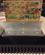
A9
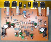
Some photos of my A9 amplifier with TL072 opamp. Offset is 0mV with TL072 and play very vell ,clear and detailed sound. With LM4562 I get -1.7 V offset and no sound on output.So the TL072 stay in amp.
Regards,
zoky2
Some photos of my A9 amplifier with TL072 opamp. Offset is 0mV with TL072 and play very vell ,clear and detailed sound. With LM4562 I get -1.7 V offset and no sound on output.So the TL072 stay in amp.
Regards,
zoky2
Attachments
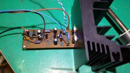
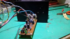
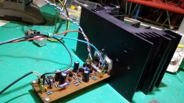

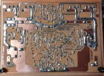
Here are some pics of one of my boards. Please look to see if you can find any errors. The board will not power up properly. I installed a 500R trimmer since the schematic shows 220R in that position. I didn't have 2W 1R so I installed 5W 0R33 emitters and I used two 1W 6K8 resistors in paralell for the 2W 3k3 resistors.
Thanks, Terry
Can you check this?
Attachments

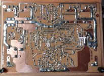
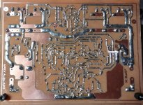
what is the value of this resistor,it should be 100 Ohm:
The last digit on the Dale resistor represents the number of zero(s) to be added. So 1000F means 100 Ohm.
Some photos of my A9 amplifier with TL072 opamp. Offset is 0mV with TL072 and play very vell ,clear and detailed sound. With LM4562 I get -1.7 V offset and no sound on output.So the TL072 stay in amp.
Regards,
zoky2
Nice work, can you compare sound of A9 with AX11 and Ax14?
Regards
The last digit on the Dale resistor represents the number of zero(s) to be added. So 1000F means 100 Ohm.
something like ceramic capacitor marking - thank You for declaring me that,i never had contact or worked with Dale resistors so actual value in number or colour marking is what i knew - up till now! 🙂 thanks again!
Thanks to everyone for taking such close looks at all the soldering. I have checked each point and all are OK. It is so difficult to get clear pictures of shiny solder without shadows. 44250 has a working board so I must keep looking. All of you in Europe and Asia are awake when I am sleeping so I have a lot to catch up on. I value all of your help. 44250 has working boards so I must soldier on and find the issues with mine. Thanks again.
Blessings, Terry
Blessings, Terry
- Home
- Amplifiers
- Solid State
- 100W Ultimate Fidelity Amplifier