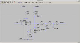
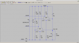
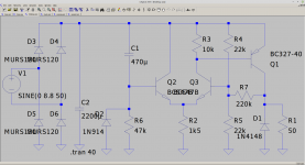
Inspired by one of Zintolo schematics, took the plunge and built a second version of this amp. Rather than having a first gain stage, use a cascade JFET (2sk170) and 12AX7 as the voltage gain stage, followed by a buffer ECC88 to drive the standard output stage which is 4x6550 and a 1650T Hammond OPT. The result is 120W rms one channel driven and 100W+100W both channels. THD I cannot measure at 40ppk at 1KHz in 8R I think is around .1%.
So please enjoy the schematics. If anybody wants I can also share the LTspice files.
So please enjoy the schematics. If anybody wants I can also share the LTspice files.
Attachments
-
 Screenshot from 2021-02-19 16-46-14.png118.1 KB · Views: 806
 -
 Screenshot from 2021-02-19 16-47-11.png84.9 KB · Views: 825
 -
 Screenshot from 2021-02-19 16-47-38.png73.5 KB · Views: 778
 -
 Screenshot from 2021-02-19 16-48-45.png103 KB · Views: 753
 -
 Screenshot from 2021-02-19 16-49-20.png119.7 KB · Views: 780


Well I would like to say being a valve amp its sounds warm. Nop. It sounds like a modern SS amp. I guess that's what happens when you make things linear. Not much blue glow either - but it looks a beast.
Yup, my 6550 beast sounds like a good solid state amp too - minus the low level high order crossover distortion. “Iron fist bass” comes to mind when describing it. The only thing “disappointing” was the lack of blue glow in the 6550’s. Tungsol, probably made on the same assembly line as your EH’s.
You trust perf boards for permanent wiring at high voltage?
You trust perf boards for permanent wiring at high voltage?
Yes that would be a good description solid bass. I have taken whole strips out where there is high voltage difference (>100V) so there's never a narrow gap. I've used this technique before and had no problems as long as you do check you have done this. You can lift then out with a knife and hot iron. I think a PCB would be much easier to construct. I know everybody here likes their own thing but putting the schematic's on gives others ideas to experiment. I guess lack of blue glow = good plate capture.
Last edited:
About 250W idle. So does not compare with a class D very well. There's a heatsink on the back of the 372LX mains transformer.
It is amazing how much solid GNFB will de-politicize the sound of an amplifier, regardless of whether based on valves, BJTs, FETs or a combination of them all. However, it also is a bit bittersweet: all that effort mostly to produce a room heater and magnificent steampunk piece of engineering art.
Myself, I like the JFET front-end, and the 12AX7 cathode followers to stiffen up their output. I might have opted for a bunch less total gain, and equally less GNFB. To 'round out' the sound toward the acoustically more 'interesting' valve harmonic form.
But that's just an old vacuum-head.
⋅-⋅-⋅ Just saying, ⋅-⋅-⋅
⋅-=≡ GoatGuy ✓ ≡=-⋅
Its about 1.5V pk for full output and the GNFB is 18dB. Using 2sk170 was the only fet with a sharp enough curve to get enough gain for the target GNFB. If you want less gain you could use something like a J112. I quite like a 'blameless amp' and its nice to do this with nearly all valves. Sadly any distortion you get back in will be odd harmonic. The circuit is very linear even with no NFB.
Last edited:
Hi baudouin0,
nice to see you developed the amp I have, making it more powerful and linear.
Have you tried CCS instead of those 33 kOhm on the drivers?
It has been the hugest improvement on that amp.
If you want to see latest version I'm using now, you can see this post:
improvements on 12AX7 12AT7 EL34 schematic?
It's 0,56% THD (simulated) at 52 Wrms with one single pair of EL34, basically only 3rd harmonic.
I will try U440 too as balanced fet.
Zintolo.
I did look at this but found that using ECC88 instead of a 12AU7 did almost as well. I was trying to simplify your design a bit as as you can see by the time you have the servo bias and the supply its quite complicated. I could not measure the THD at 40V ppk and oddly the distortion actually dropped at higher powers so was quite happy without the CCS. I have to say a big thanks for putting up the circuit as I would not have built it otherwise.
I did look at this but found that using ECC88 instead of a 12AU7 did almost as well. I was trying to simplify your design a bit as as you can see by the time you have the servo bias and the supply its quite complicated. I could not measure the THD at 40V ppk and oddly the distortion actually dropped at higher powers so was quite happy without the CCS. I have to say a big thanks for putting up the circuit as I would not have built it otherwise.
baudouini0,
Nice amplifier! Good job!
1. Reliability
Each 6550 is fixed biased.
Each 6550 uses 100k g1 resistors
Each 6550 specifies 50k g1 resistors
Use very Robust 6550 tubes.
Or, find that some 6550 tubes will be Busted.
Your Tubes Mileage May Vary
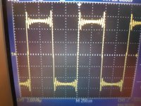
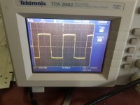
2. Ringing 1 kHz
That scope photo of a 1kHz square wave, has Pre-transition ringing, and Post-transition ringing.
That photo looks like a CD player's digital filter artifact.
Or a sound card signal that has a digital low pass filter?
It does not look like amplifier ringing (I never saw an amplifier that had Pre-transition ringing).
. . . Try doing the square wave test again, but this time with a real analog square wave.
Thanks!
Nice amplifier! Good job!
1. Reliability
Each 6550 is fixed biased.
Each 6550 uses 100k g1 resistors
Each 6550 specifies 50k g1 resistors
Use very Robust 6550 tubes.
Or, find that some 6550 tubes will be Busted.
Your Tubes Mileage May Vary
2. Ringing 1 kHz
That scope photo of a 1kHz square wave, has Pre-transition ringing, and Post-transition ringing.
That photo looks like a CD player's digital filter artifact.
Or a sound card signal that has a digital low pass filter?
It does not look like amplifier ringing (I never saw an amplifier that had Pre-transition ringing).
. . . Try doing the square wave test again, but this time with a real analog square wave.
Thanks!
Last edited:
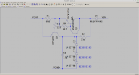
It is servo bias rather than fixed bias so the cathode current is measured and the grid voltage adjusted automatically. So I can use the leak resistors as if it were cathode bias so 100k is fine.
Interestingly one 6550 I has ended up with -59V on grid and still took 40ma. This one had started to leak on a previous amp. So I chucked this. The ECC88 driver could be adjusted to drive 25k by increasing current to drive fixed bias if you wanted. It in may be worth adding a LED on each servo bias. This would indicate if the grid ended up at max negative voltage and is a good indication of a 6550 failure towards short. Or a meter with an 8-way switch.
The square wave I need to get a sig gen in as this was a 48KHz sampled source well observed. The unit will deliver full power at 10KHz.
Last edited:
"The square wave I need to get a sig gen in as this was a 48KHz sampled source well observed"
Whew! My first thought was that you'd invented a time machine, with ringing preceding the gong.
YOS,
Chris
Whew! My first thought was that you'd invented a time machine, with ringing preceding the gong.
YOS,
Chris
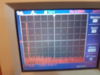
So I got an old sig gen TG501 and looked at the square wave. One channel was OK and the other marginal. I have moved the dominate pole down a bit C11 now 330pF rather than 220pF. These are the new plots for both channels. Having a band limited signal does not show up the problem - thanks.
Attachments

- Home
- Amplifiers
- Tubes / Valves
- 100W + 100W amp to share