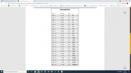
I want to construct a shunt stepped attenuator of 100K value. The series resistor will be fixed at 100K. I now need the resistor values to ground for a 24 step switch. I have conflicting values from a theoretical table and an actual Khozmo 48 step attenuator where I've used alternate steps. I also have a 22 step Alps attenuator. I've tried to average them out. (You could also read the values backwards)
Can you suggest a "best" solution?
Can you suggest a "best" solution?
Attachments

Last edited:
Is the load on the attenuator just a tube grid? Otherwise, the load will affect the attenuation.
Fine steps at low volumes are not needed, and are wasteful of the limited number of switch positions.
Fine steps at low volumes are not needed, and are wasteful of the limited number of switch positions.
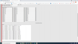
Few more attached, spreadsheet shows the Valab vs Goldpoint values. I always start with the Goldpoint values, then tailor them to my needs. Basically i work out the nominal range where the pot will live in circuit, then change the values around it for 1db steps.
Attachments
Thanks mcandmar - useful data. The values are different from the Alps and Khozmo I posted. Here's the values for the 12th step:
Merlin's - 1036 (24 step)
Valab - 2100 (23 step)
Khozmo - 3600 (24 step)
Goldpoint - 4990 (24 step)
Alps - 11200 (22 step)
The Khozmo looks to be about the "middle" of the range.
This indeed comes before the grid of the input tube. Looks like the values are chosen for practical results rather than pure theory.
.
Last edited:
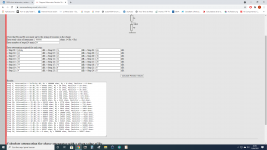
I do the math to work out the DB attenuation for each dividor, then tried to get as close to 1db for each step. However, the resistor values you have to play with are dictated by availability. Some manufacturers just stick to standard E24 resistor values.
When i built mine i used Dale RN60 series and used the Mouser parts system to see what values were available. This is where the spreadsheet was invaluable as i could key in the different resitor values and see what the DB attenuation was, and the total resistance across the dividor. The last pot i built (50k for 01A pre) i had hours of fun tweaking the resistor values to get each value as close to ideal as posible. But your level of OCDness may differ 🙂
When i built mine i used Dale RN60 series and used the Mouser parts system to see what values were available. This is where the spreadsheet was invaluable as i could key in the different resitor values and see what the DB attenuation was, and the total resistance across the dividor. The last pot i built (50k for 01A pre) i had hours of fun tweaking the resistor values to get each value as close to ideal as posible. But your level of OCDness may differ 🙂
This is indeed for an 01A or 26 preamp, so your experience here is valuable!
How did it all work out in practise? What values gave you the best real-word attenuation for your system?
Did you think of a 100K attenuator instead of a 50K one? Did you build a ladder or a shunt? The shunt looks a lot simpler for pretty much the same effect.
How did it all work out in practise? What values gave you the best real-word attenuation for your system?
Did you think of a 100K attenuator instead of a 50K one? Did you build a ladder or a shunt? The shunt looks a lot simpler for pretty much the same effect.
I did, and debated over 50k or 100k for a while and came to the conclusion that 50k would work fine with my sources in that they could all drive the load without any low or high frequency roll off. In testing i was seeing a flat frequency response right out to 48khz where my test setup tapped out, so the 50k input + Millar capacitance did'nt even come into play. It's six of one, half dozen of the other really. Most DAC's can drive down to 10k loads with no issues so really only a concern for older tube based sources.
As for real world volume range, i tend to live just before half way with my DAC & FM tuner sources which is perfect.
I always go for stepped ladder attenuators as there is less in the signal path. I just dont like the idea of shunt style where you would have a dozen or so resistors in series, i work on the basis the fewer components in the signal chain the better.
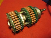
As for the units themselves (i probably shouldn’t say this) but my favorite by far are the original Goldpoint stepped ladder units. I just love how tactile they feel, and are very high quality switches. They stopped making them in the late 90's so i snap them up whenever i see them. It is rather tedious to build, working out all the resistor values, matching the physical resistors into pairs, then soldering all 96 of them into the switch unit. Many many hours....
As for real world volume range, i tend to live just before half way with my DAC & FM tuner sources which is perfect.
I always go for stepped ladder attenuators as there is less in the signal path. I just dont like the idea of shunt style where you would have a dozen or so resistors in series, i work on the basis the fewer components in the signal chain the better.
As for the units themselves (i probably shouldn’t say this) but my favorite by far are the original Goldpoint stepped ladder units. I just love how tactile they feel, and are very high quality switches. They stopped making them in the late 90's so i snap them up whenever i see them. It is rather tedious to build, working out all the resistor values, matching the physical resistors into pairs, then soldering all 96 of them into the switch unit. Many many hours....
Attachments
Thanks for the input. By "shunt" I mean a single series resistor for the input, e.g. 100k. The "shunt" resistors are the 24 resistors to ground if I understand the terms correctly. A "ladder" as I understand it replaces the single series resistor with 24 resistors which more accurately maintain the 100k input resistance. A "series" attenuator has 24 resistors in series, so several are in play. this kind of mimics a conductive volume pot but with resistors.
.
.
Last edited:
- Home
- Source & Line
- Analog Line Level
- 100K shunt attenuator, resistor values?