The "port" is actually just a rectangular hole in the wall at the end of the line and is called a terminus. It would have the same cross-sectional area as the end of the line but doesn't have to be the very same dimensions and it may be better for it to have a smaller aspect ratio while keeping the same cross-sectional area as the end of the line. As to any improvements, note that this line has a large volume, much larger than the ~70 liters maximum you were hoping for. The volume can be reduced at the expense of F3 rising (that's why I much preferred the SB 10-incher; it can play lower in a smaller volume than this Peerless).
Paul
Paul
Thanks Paul! Look great. Sorry not to respond earlier - I haven't been getting email notices.
Work will proceed on this model if an improvement isn't found.What would the port be like?
OK Paul, I understand. I've built that sort of box before.
Let's see if I can get the driver changed, if it's not too late.
GM had a look at you results and agrees that your sim is good for the Peerless. Just that the Peerless isn't really right for this box. 🙁
Let's see if I can get the driver changed, if it's not too late.
GM had a look at you results and agrees that your sim is good for the Peerless. Just that the Peerless isn't really right for this box. 🙁
I don't want to overly influence your driver choice, you understand. The end result is more important and must take into consideration all factors, like your box size preferences, hoped for performance, your budget, etc. I'm happy to model a TL for either driver. Just so it's perfectly clear, I modeled these TLs with their published T/S values. Whatever driver you choose, if you have another, presumably more realistic, source of T/S values, make sure you get them to me.
Paul
Paul
OK Paul, I understand. I've built that sort of box before.
Let's see if I can get the driver changed, if it's not too late.
GM had a look at you results and agrees that your sim is good for the Peerless. Just that the Peerless isn't really right for this box. 🙁
Further TL modeling for SB10
To fit into the 2.5 ft3 box 30" high, I modeled a shorter, single-fold, tapered TL that's 60" long and tapered at 21:1. The line starts at 12"W x 10.5"D and ends at 12"W x 0.5"D. The terminus would have the same area as the end of the line but I recommend it be 6"W x 1"H. The woofer's center is located 12" from the beginning of the line, and the first half of the line is stuffed at 1 lb/ft3 (requiring ~27 ounces total of polyester-type stuffing). I've attached the modeled system response graph for a 2.83-volt input with F3 at ~27 Hz. With a 50-watt input, the output SPL is ~106 dB, the woofer reaches Xmax plus 15% at ~17 Hz, and the terminus air velocity peaks at 5% of the speed of sound (17 m/s) at ~22Hz. I think this is the best overall performance that can I can come up with for your required box size and shape.
Paul
Attachments

Last edited:
Sure wish this forum would allow one to edit a post a lot longer than just in the first 30 minutes after the initial posting without having to enlist the aid of a forum administrator.🙁 Anyway, I wanted to add that the internal dimensions of this 2.5 ft3 box would be 12"W x 12"D x 30"H. Also, while what I modeled is the best I could come up in this size box, perhaps someone else could do better. Last, I modeled with 0.4 ohms assumed to be in series with the woofer to represent the d.c. resistance of a series crossover inductor.
Paul
Paul
To fit into the 2.5 ft3 box 30" high, I modeled a shorter, single-fold, tapered TL that's 60" long and tapered at 21:1. The line starts at 12"W x 10.5"D and ends at 12"W x 0.5"D. The terminus would have the same area as the end of the line but I recommend it be 6"W x 1"H. The woofer's center is located 12" from the beginning of the line, and the first half of the line is stuffed at 1 lb/ft3 (requiring ~27 ounces total of polyester-type stuffing). I've attached the modeled system response graph for a 2.83-volt input with F3 at ~27 Hz. With a 50-watt input, the output SPL is ~106 dB, the woofer reaches Xmax plus 15% at ~17 Hz, and the terminus air velocity peaks at 5% of the speed of sound (17 m/s) at ~22Hz. I think this is the best overall performance that can I can come up with for your required box size and shape.
Paul
Last edited:
Hey Paul, no worries and thanks for the work. Looks like the Peerless order will get canceled and the SBs ordered instead, so all is good.
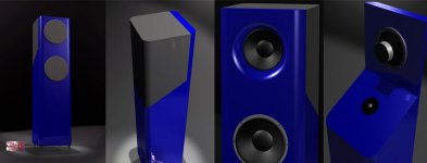
The box will look something like the rendering below with overall dimensions approx. 14x14x48" So I figure ~32" inside box height. The idea would be to do one or more flods or bends on the inside.
What do you think?
The box will look something like the rendering below with overall dimensions approx. 14x14x48" So I figure ~32" inside box height. The idea would be to do one or more flods or bends on the inside.
What do you think?
Attachments
Since it emits low frequencies , putting it downwards should add a light lowpass ,being omni it should be no problem .
The trick would be to overcome the necessary delay from speaker's transient start to terminus ...
And you didn't follow what Paul said ,to put the speaker at about 12" from the closed end .
🙂
The trick would be to overcome the necessary delay from speaker's transient start to terminus ...
And you didn't follow what Paul said ,to put the speaker at about 12" from the closed end .
🙂
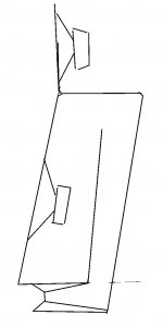
Yeah, therein lies the crux of the matter, to get a bottom vent and acceptable driver height requires at least three folds, so will the driver even fit at the extreme top, much less further down once the baffles are in?
The driver is ~3.94" deep on a ~0.75" baffle, so add ~1.5" for the internal baffles minus ~12.5" i.d. = ~7.06" of acoustic depth. At a glance, probably not really enough unless the driver is at the extreme top.
Considering its diminutive footprint though, 0.5" thick baffles would probably be fine if BB or Apple ply and maybe even the sides and back too with some minor bracing using alum. angles that take up no audible amount of space.
GM
It does not have to be a bottom vent, that was just an idea to hide it. Complicated internals are not a big issue, if there is a way to get it all to fit. 
How about a good old TQWT with the vent on the bottom?
How about a good old TQWT with the vent on the bottom?
Yeah, a reverse taper like PK's or a Daline is probably the way to go and considering he wants complexity, I'm leaning towards the latter if it can be made to work. It would stiffen up the sides a bunch too. Might even be able to get away with ~0.38" thick BB ply internal baffles, side walls with maybe just 4-6 dowels running from front to back to pinch it all together. 😀
GM
GM
So what do we think? A single fold, single internal baffle like a calssic TQWT, or go with a longer path - like 2 folds?
Sideways line?
Sure, either would do. Any idea on line length or just divide it up? Terminus?
Huh? His is what I call a TQWT merely to differentiate it from a simple straight taper TL, it starts out big at the closed and tapers down to a much smaller terminus, so would be basically folded up like your example except if downfiring it of course wouldn't have the last fold to get a front exit.
Any time a driver's specs dictates a very long vent, morphing the box/vent into a TQWT will perform better overall.
Anyway, from your 3D drawing, how much gross space available is there since it's not a simple rectangle?
GM
IMO it's not a TQWT but a ML-TL .
What you drew is clearly not a MLTL, but a ML-TQWT.
GM
My guess is anywhere from 3ft^3 to 3.5ft^3 depending on how deep it's built. Nominal is 14" deep, but 16 is certainly reasonable. With that I'm figuring 1/2" ply, as the baffles should add lot of bracing.
So let's work within 3.5 cubic feet, ~100L. What can we do with that given the SB-10?
Specs here: https://www.madisound.com/store/product_info.php?products_id=8303
So let's work within 3.5 cubic feet, ~100L. What can we do with that given the SB-10?
Specs here: https://www.madisound.com/store/product_info.php?products_id=8303
- Status
- Not open for further replies.
- Home
- Loudspeakers
- Multi-Way
- 10 woofer for transmission line?