Now that you have measured it, you know that "Sag Happens" 😉.OK, Apologies to all, I just had to confirm an affliction of driver sag for myself.
Measuring as best I can, I came up with a value of 15-16mm on the "old" horizontally stored driver, open to the elements indoors
Measured values of the vertically stored NIB driver gets me 13mmm....a sag value of 2 to 2.5mm.
I had to rework the spiders in some passive radiators, that had been stored face-down, once.
That was FUN!
That was FUN!
ALL my speaker drivers, including subs and basses have been packed, stored and transported in horizontal position. Many high-class commercial and diy designs have drivers set horizontally.
I don't think it is so bad, not ideal though.
I don't think it is so bad, not ideal though.
regarding cone sag
what if a amp signal is applied
will it make any difference
but with a music signal i suppose cone sag stops ... while it lasts
I take it that while playing/moving there cannot be any cone sag
at least on a horisontally mounted driver
but when playing, cone sag might get worse when vertically mounted 😀
Just to check, won't vertically stored drivers sag one way at the bottom and the other way at the top, meaning the pole would be out of alignment with the voice coil gap?
There's two versions of "cone-sag" being discussed here.
1. The immediate deflection of the cone caused by the driver being mounted with the cone facing up or down. This is reversed as soon as the driver is returned to a vertical position. The first one can be calculated.
2. The gradual and increasing permanent deflection of the cone caused by the driver being left for a long period with the cone facing up or down. This cannot be reversed by returning the driver to a vertical position. This permanent deflection cannot be calculated, and IMO depends primarily on the environment and the material the driver's spider is made of.
The JBL xx00GTis seems to have suffered badly with (2), and these were pretty expensive drivers. OTOH, my cheap Infinity 122.7W drivers with their heavy cones seem to have not suffered at all over approximately the same period of use in my car. Their spiders are made of a noticeably different material to the ones used in the older GTi series.
As for the THs with the drivers mounted with the cones facing up or down, the quick and easy solution to cone-sag phobia is to just lay them on their sides. They may even sound better (I won't bother to go into the explanation).
Thank you for your reply 🙂
Given there are subwoofer manufacturers that specifically design down-firing subwoofers, would it be correct to assume that driver sag would be 'better' that way? i.e. the cone will eventully rest further away from the backplate, therefore you would be less likely to run the cone assembly into the hard bits of the driver than you would be if the driver was up-firing and therefore sagging nearer to the spider etc?
Due to size/placement constraints I really don't think I will be able to design vertical drivers into the PPSL box I am attempting to design, so I guess I'm looking or some crumbs of comfort!
Given there are subwoofer manufacturers that specifically design down-firing subwoofers, would it be correct to assume that driver sag would be 'better' that way?
no, they just don't care
other than it sells better
I think it's a fact that down-firing woofers 'excites' the floor more
and you leave the store with the impression of something really great
at home, you may either love it, or get tired of it
but who says it should last forever 😕
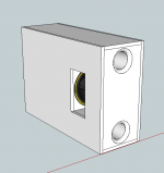
I know this thread has kinda headed off in a different direction but I though I would post an update to my build.
After I built the enclosure I found I had some issues with port noise and I had an air leak around one of the drivers. This gave me more than enough excuse to try again and incorporate a few design changes.
I've attached some images of my Mk II design. I've re-positioned the drivers so they are vertical, this should eliminate any cone sag issues. I've also changed the ports over to a round shape with a generous amount of flare at each end. Hopefully that will take care of the port noise I was seeing.
Attachments

Chuffing means you need bigger ports (and they then have to be longer).
My dual 4.3mm Xmax 18’s in a 16ft3 box tuned to 27hz NEEDED a 12” port.
That's a bunch of air slooshing through the port at 27hz.
How much Xmax are those 10’s ?
And what frequency are you tuning to ?
Nice looking box. Maybe the ports are seeing some frictional losses due to being so close to the box edges. I can't remember if the slot port "looks" longer or shorter than an equal sized round port (not at a box edge). And a slot loading on the floor is different than a round port coming out of the box 1' off the ground. It'd be nice to test and measure this stuff.
The drivers have a 4.5 mm xmax, so not exactly excursion monsters. I determined the port size using a formula I found and now I can't remember where. The formula is Vd x Fb x .02 = area of the port in square inches with Vd being the drivers displacement in cubic inches and Fb being the tuning frequency of the enclosure.
The enclosure as it is in the proposed design is 3.5 cubic feet net volume and is tuned to 30 Hz.
The enclosure as it is in the proposed design is 3.5 cubic feet net volume and is tuned to 30 Hz.
either way, try for larger ports, as long as you can fit.
That's the trouble with smaller boxes (3ft3 vs 10 or 15ft3). It is difficult to get a big enough port that isn't longer than the box but also below 24" (pipe resonances).
I cringe seeing a 15" 14mm xmax subwoofer tuned to 20hz with a pair of 4" ports.
But, my opinion.
That's the trouble with smaller boxes (3ft3 vs 10 or 15ft3). It is difficult to get a big enough port that isn't longer than the box but also below 24" (pipe resonances).
I cringe seeing a 15" 14mm xmax subwoofer tuned to 20hz with a pair of 4" ports.
But, my opinion.
I know this thread has kinda headed off in a different direction but I though I would post an update to my build.
After I built the enclosure I found I had some issues with port noise and I had an air leak around one of the drivers. This gave me more than enough excuse to try again and incorporate a few design changes.
I've attached some images of my Mk II design. I've re-positioned the drivers so they are vertical, this should eliminate any cone sag issues. I've also changed the ports over to a round shape with a generous amount of flare at each end. Hopefully that will take care of the port noise I was seeing.
Nice!
How long are those ports?
Nice!
How long are those ports?
Including the flares at both ends they are 19.25"
are you sitting right on top of the subwoofer ?
Do you hear chuffing when music is playing ??????
I've pounded the schmoo out of my 8mm dual 15's run up to 400 watts crossed at 750hz (4" port tuned to 27hz) and never heard a problem. My buddy easily hears chuffing using same box but both ports open used as a sub.
The snell dual 12" (maybe using 15-22mm xmax drivers) uses a pair of 4" ports.
Way Down Deep III Snell ICS Sub24 | Sound & Vision
There are mach numbers for air speed, try looking up those avenues.
Port Flares
One thing about round ports is people will buy those so called "Flared" 4 inch port kits with the radiused ends, and that is not really the best shape for a port termination.
The flare is an impedance matching device, matching the high velocity air motion in the port with the still air half a foot away from the port end.
With a radius, the walls get exponentially more angled away from the axis of the port tube.
There is flow separation from the walls as you get to a certain angle from the flow axis and a high velocity.
In many cases, if the port is marginally sized, the effective diameter of the port is smaller than the straight round section due to the turbulence set up by the flow separation.
.
A port flare should be more like a taper with maybe no more than a 45 degree included angle.
.
A good approach to port termination can be found by studying rocket nozzles.
They do the same thing, take high pressure gasses and expand them to be the same pressure
as the ambient atmosphere that they operate in. (impedance matching)
It seems a little counter-intuitive but that gives rocket engines the highest efficiency.
Or study 2 stroke expansion chambers.
Anyway, IMHO at least
Dave
......[/end rant]
Norman:
I only heard chuffing when listening to a sine wave, so it was a bit of a worse case scenario. My current enclosure uses a slot port and my suspicion is that the slot port is more susceptible to chuffing than round ports are. That one of the things I'm going to be testing out with this new enclosure.
Shadydave:
I've seen other posts you have made regarding port flares and it definitely gives me something to think about. My current plan was to use a 3/4" round-over bit in my router to cut the flare at each end. I'd like use a 1" round-over bit but I don't have one. Maybe I'll pony up and get one I can certain see how a 45 degree angle would produce a more laminar flow but I worry that disturbance would occur where the angle first begins. I'm not sure how you could produce a flare and begins at a low angle and expands to 45 degrees but doesn't go beyond that like a normal round over does. I guess I could cut both shapes from different sheets of material and then combine them, but that's getting to be a lot of work.
I found your comparison to 2-stroke expansion chambers interesting. I just wonder a what point the flare becomes so long its becomes more like a horn and makes it difficult to calculate the proper port length for tuning.
- Status
- Not open for further replies.
- Home
- Loudspeakers
- Subwoofers
- 10" PPSL Vented Enclosure Design Help