Thank you, Edmond! Very interesting and I stand corrected. So both the original method network and Sandy's sketch work, albeit with different expressions for the notch frequency.
Using the "virtual ground" analysis on the original network, each arm has radian corner frequency of 1/(2 Pi RC) radians/s = 1/(4 Pi RC) Hz.
Thanks again.
Using the "virtual ground" analysis on the original network, each arm has radian corner frequency of 1/(2 Pi RC) radians/s = 1/(4 Pi RC) Hz.
Thanks again.
Make sure that the equipment which drives the passive filter input, has a very low output impedance. I'd recommend Zout_driver <= (R / 50) where R is the smallest resistor in the filter circuit.
Also make sure that the equipment which is driven by the passive filter output, has a very high input impedance. I'd recommend Zin_receiver >= (R * 50) where R is the smallest resistor in the filter circuit.
Otherwise you'll inadvertently reduce the notch depth and change its center frequency.
Of course these restrictions disappear if you use an active filter instead of a passive filter. Think of them as the "cost" of insisting upon all passive.
Sure. You finally discovered that too. Better late than never.Едно и също е.
Is that so?Просто човек е по-удобен за използване
BTW: Posting in a language other than English without a translation is not allowed (see terms and rules).
No.[...]
Also make sure that the equipment which is driven by the passive filter output, has a very high input impedance. I'd recommend Zin_receiver >= (R * 50) where R is the smallest resistor in the filter circuit.
Otherwise you'll inadvertently reduce the notch depth and change its center frequency.
[...]
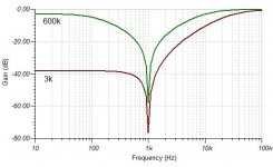
I've been experimenting with this Hall type notch filter as described in THIS ARTICLE. I duplicated the circuit in figure 6. on breadboard. Why is my output leading to the notch~40 dB down from what I expected?


Here is the simulation of your Hall network for two impedances of the ADC inputs - 600 kOhm (instrument input) and 3 kOhm (mic input).I've been experimenting with this Hall type notch filter as described in THIS ARTICLE. I duplicated the circuit in figure 6. on breadboard. Why is my output leading to the notch~40 dB down from what I expected?
Martin
Attachments
Last edited:

With the input of the Focusrite set to MIC I'm getting the FR as simulated above. However, when I do a 1k loopback with the notch filter in the circuit the spectrum analyzer shows a spike at 60Hz and all of it's harmonics. There is no connection to 60Hz AC mains, so where could this distortion be coming from?


The room is full of it, even if not wire-connected.spike at 60Hz and all of it's harmonics. There is no connection to 60Hz AC mains
Bring it to my back yard, a mile back. Or a mile the other side of George's. The 60Hz hash will be far less.
It looks like ground loop noise/hum.With the input of the Focusrite set to MIC I'm getting the FR as simulated above. However, when I do a 1k loopback with the notch filter in the circuit the spectrum analyzer shows a spike at 60Hz and all of it's harmonics. There is no connection to 60Hz AC mains, so where could this distortion be coming from?
View attachment 1127102View attachment 1127103
You can try to disconnect GND (shielding) from notch filter in one of your cables - their GNDs are connected in your Focusrite already and acts as antenna loop to pick-up the hum and noise.
Martin
Late to the party – but this Hall notch filter is very good!
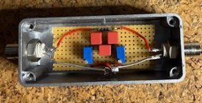
Big thanks to euro21 for sharing the LTspice file. I built the Hall notch filter in hardware based on the LT Spicel schematic and took great care in matching components.
Build Details:
- Resistors 120k
- Capacitors: Hand-picked from over 60 pieces to achieve <0.1% matching
- Trimpots: R2 = 6.055 kΩ, R3 = 13.945 kΩ – measured with 4-wire technique using a Keysight 34461A
- Enclosure: Metal housing with shielded layout and BNC connectors
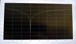
📈 Performance:
- Notch frequency: Precisely 1000.5 Hz
- Attenuation: –84.5 dB at 1 kHz (Keysight)
- Input signal: 1 Vrms input
- Measurement gear: Keysight 34461A, Rigol DHO804, ARTA with 10X probe
Thanks again for sharing this gem! 🙂
Attachments


Last edited:
cosmo61, well worth checking at lower and higher temps to see how much all the component drifts affect the notch - may give peace of mind over time, or make you check the local temp when next using it.
I built the classic Twin-T notch filter based on @Elvee idea:
https://www.diyaudio.com/community/threads/my-take-on-the-passive-notch-filter.315406/
I modified it a bit so that I get constant -5 dB attenuation at all harmonics from 2nd. In the practical build I found that the 330 mH potted core inductor is sensitive to stray magnetic field, magnetic shielding is recommended. Attached is my version.
Attachments

Good point! This filter was tested at around 20 °C.cosmo61, well worth checking at lower and higher temps to see how much all the component drifts affect the notch - may give peace of mind over time, or make you check the local temp when next using it.
I typically only use it for short measurement sessions—max 30 minutes—so temperature drift hasn’t been a concern.
But I might still do a quick test by warming the aluminum enclosure a bit, just to see how stable the notch is.
icsaszar
Thanks for sharing! I actually started with a classic Twin-T as well.
Your modification to maintain constant –5 dB attenuation across harmonics sounds clever.
Thanks for sharing! I actually started with a classic Twin-T as well.
Your modification to maintain constant –5 dB attenuation across harmonics sounds clever.
Last edited:
Theoretically, 🙂 with the selected components, the temperature drift should be minimal.
With WIMA FKP2 caps, Bourns 3296W trimmers, and Yageo MF0207 resistors, a +10 °C shift from 20 °C should give:
Still well within excellent range – mine measured –84,5 dB at 20 °C.
With WIMA FKP2 caps, Bourns 3296W trimmers, and Yageo MF0207 resistors, a +10 °C shift from 20 °C should give:
- ~0.05 % drift from caps and resistors (50 ppm/°C)
- ~0.1 % from the trimmers (100 ppm/°C)
Still well within excellent range – mine measured –84,5 dB at 20 °C.
- Home
- Design & Build
- Equipment & Tools
- 1 kHz passive notch filter