How did you determine this on the FT3? I would like to try itThanks Frentec. I figured it out after realizing that the input impedance of the AVC or even if the 01A is directly connected to a power amp would be several multiplies of the SF. Not much difference tonally with the Duelund connected either way but noticed that instrument placement was a bit better with the outer foil side towards the SF so have left it that way.
After having done this I went ahead and figured out which is the outer foil side on a FT3. To my surprise the FT3 sounds decidedly better with the outer foil side to the SF as opposed to the other way around.
nash
With a pre, poweramp and speakers connected you need to connect the cap to a line input. This is easily done by plugging in an RCA cable into an input of a preamp or integrated amp that has a volume control. Using crocodile clips connect the RCA cable signal pin to one end of the cap and the signal ground to the other end of the cap. Turn on the amps and turn up the volume till you hear a hum, noting how loud it is.
Next, turn off the amps and reverse the leads to the cap. Turn on the amps again without changing the volume and note whether the hum is louder or softer. Keep the leads in the position where the hum is softer and mark the end of the cap that is connected to the signal ground. This is the low impedance point and where the outer foil is connected.
You may want to mark the cap as it was originally connected to compare.
nash
Thank you.With a pre, poweramp and speakers connected you need to connect the cap to a line input. This is easily done by plugging in an RCA cable into an input of a preamp or integrated amp that has a volume control. Using crocodile clips connect the RCA cable signal pin to one end of the cap and the signal ground to the other end of the cap. Turn on the amps and turn up the volume till you hear a hum, noting how loud it is.
Next, turn off the amps and reverse the leads to the cap. Turn on the amps again without changing the volume and note whether the hum is louder or softer. Keep the leads in the position where the hum is softer and mark the end of the cap that is connected to the signal ground. This is the low impedance point and where the outer foil is connected.
You may want to mark the cap as it was originally connected to compare.
nash
Now I'm on a mission 😁
Can anyone tell me what the low impedance side of the capacitor on Ale's gyrotor is?
Last edited:
If you mean connecting the cap to the gyrator, the gyrator will still be the lower impedance side: presumably you are connecting the 01A pre to a power amp which will have a much higher impedance. So outer foil side to gyrator output. I think this is what you are asking.
Sorry.If you mean connecting the cap to the gyrator, the gyrator will still be the lower impedance side: presumably you are connecting the 01A pre to a power amp which will have a much higher impedance. So outer foil side to gyrator output. I think this is what you are asking.
I did not specify.
I was asking about C1 on the gyrators board.
https://i0.wp.com/www.bartola.co.uk/valves/wp-content/uploads/2019/02/IMG_1947.jpg
Don't forget outer foil also makes a difference with the cap on the Gyrator Board, it needs to be toward the MU Resistor for best results. I have a common supply with 2 Preamps, one is 2P29L with no source foillower, the other 01A with Source Follower,At first I felt that the FT3 was a distant second to the Duelund but after determining the outer foil side of the FT3 and connecting it to the SF(was reversed previously) I rank it a close second.
The timbre of most instruments sound more appealing with the Duelund, especially strings. For the first time I can distinguish the double bass within an orchestra. The Duelund seems to go higher at the high end and lower at the low. Slight less muddiness in the lows; in a piano trio one can more clearly make out the cello from the piano when low notes are played together.
The Duelunds are 25% off at pcx presently.
nash
the plate side where the Mu resistor is where the outer foil should be connected, it does make a difference.How did you determine this on the FT3? I would like to try it
There is only the 10R resistor between C1 & Anode, so outer foil connected there.Don't forget outer foil also makes a difference with the cap on the Gyrator Board, it needs to be toward the MU Resistor for best results. I have a common supply with 2 Preamps, one is 2P29L with no source foillower, the other 01A with Source Follower,
the plate side where the Mu resistor is where the outer foil should be connected, it does make a difference.
Thank you.There is only the 10R resistor between C1 & Anode, so outer foil connected there.
I went with my gut feeling here... or wild *** guess but I got it right.
I had an FT3 on the board and change it for a Miflex . It was a good change for me in my system.
I thought I'd provide a little update that might be of interest/useful to others.
So this is 01a built with Ale's gyrators, Rod's filament supplies and source follower.
I recently built a new power amp and it has higher gain than what I was using before. I noticed some hiss from one channel. I really wasn't sure if it had been there a while, or if it had grown over time, it wasn't that noticeable with lower gain amps. Anyhow, I started to do some reading around, seeing had other people encountered this, and there really wasn't much out there. Most hiss reports are due to poor connections, high gain circuits, maybe semiconductors at end of life or running hot.
So I thought I would open it up and see what the story was - and I started by checking all measurements. Turns out the anode current was way down on the noisy channel at 1.3mA and would not adjust upwards. The valve was worn out.....
Popped a new valve in, set filament voltage and anode current and the hiss is gone.
I have to be honest and say I didn't notice any big degradation in sound quality but listening today after replacement there is an added bit of depth and sparkle to it. Not much, but noticeable - maybe its just confirmation bias.
Anyway, thought I'd post here and relate my experience as there wasn't any mention of this anywhere else as I googled about.

I see some (including Ale) are using the AVC after the preamp (with gyrator and SF).
My question is: 1) are you using the standard Slagle AVC 2) are you all using the low gain version (2x) of the preamp or somewhat higher?
According to the AVC FAQ, the AVC has a maximal input "12V @ 20Hz" https://intactaudio.com/atten_FAQ.html
But then, on the forum on 2015, D. Slagel writes " I think the bulk of the distortion was from the AC levels on the autoformer. They are intended for line level use so 2V or so input. 4V @ 20hz gives about 1% distortion at 20hz. The only info at 20hz in music is subharmonics and I have yet to see full signal output at that frequency." Link (form the context, this should be 2V RMS)
Does anyone know if the design was changed to accommodate a higher voltage since then?
And then, even if its ok with for the AVC, what are the advantages of placing the AVC after the preamp (noise, etc?
I'm afraid that 01a unable to drive few hundred Henry inductance (AVC/TVC) without any shield (SF or CF).
AVC/TVC usually use high permeability core (without or with minimal air gap), thus at 20Hz only few Volt would grow distortion and causes saturation.
Are you read Dave forum?
https://forum.intactaudio.com/viewforum.php?f=8&sid=0e7dee458afdb4cb18dfefdd6874aad8
AVC/TVC usually use high permeability core (without or with minimal air gap), thus at 20Hz only few Volt would grow distortion and causes saturation.
Are you read Dave forum?
https://forum.intactaudio.com/viewforum.php?f=8&sid=0e7dee458afdb4cb18dfefdd6874aad8
I'm afraid that 01a unable to drive few hundred Henry inductance (AVC/TVC) without any shield (SF or CF).
Yes, it would be with a SF.
Reading older posts form the Intact Audio forum I found his one (Nov. 2006):
"I have been measuring the autoformers a bit lately and want to "somewhat" revise the maximum input signal spec given in the FAQ. I came up with the number in the FAQ by being conservative and adding a buffer in case anybody ever measured them.
It has become clear to me that I am the only person measuring and documenting these things and since we are all friends here, i'll come clean.
the math suggests that the 8V @ 20hz number listed in the FAQ will result in a flux density of about 3900 gauss or about 1/2 of what 80% nickel is supposed to saturate at. At the time my test equipment confirmed this to be close so i proceeded on the side of caution.
Since I had a pair on the bench tonight, i decided to look a little closer where things get ugly. From the test equipment on hand (much better than the stuff i had 7 years ago when the 8V@20hz number originated) i came to the conclusion that 7V@10hz (same as 14V@20hz) is the corner of bad behavior. Given that this translates to a flux of 6800 gauss and the quoted saturation number of nickel in that vicinity i tend to trust that number. To completely justify my rash behavior, i'll go back to some of my recent experiments with tracing the BH loops of various core materials which told me that 80% nickel the way i use it is very linear from very small signals right up to saturation.
So as it stands now, anyone reading this has my permission to try the autoformers at much higher levels... and remember that 14V@20hz is 28V@40hz and 280V@400hz.
To really throw a spanner in the works, I keep going back to mr. partridge who suggested (to me at least) among other things that the peak power in audio never happens at low frequencies and that using 50hz as the lowest frequency of interest gave enough justification for using intentionally gapped PP outputs.
sure it may be apples to oranges, but at a conservative 50hz, i'll stand by 35V rms as a max which translates to 50V peak. makes me wonder what an autoformer would sound like driving and adjusting the volume on the grid of a 75TL
dave"
It all boils down to source impedance, primary inductance, and rated transformer level in dBu (or Vrms) at specified distortion at lowest frequency.I'm afraid that 01a unable to drive few hundred Henry inductance (AVC/TVC) without any shield (SF or CF).
AVC/TVC usually use high permeability core (without or with minimal air gap), thus at 20Hz only few Volt would grow distortion and causes saturation.
Are you read Dave forum?
https://forum.intactaudio.com/viewforum.php?f=8&sid=0e7dee458afdb4cb18dfefdd6874aad8
TVC are usually line level, meaning that their specs are guaranteed for 600 Ohm source. Can such transformer be driven by a 10K source, such as 01A? It depends. It warrants closer look.
Let's assume it is a good unit having 200 H inductance (huge overkill for 600 Ohm, but that's what they are!). At 20 Hz, the impedance is 24 K. So, if this TVC is driven by a 24 K source, the response will be down -3 dB at 20 Hz. With 10 K source, -3 dB point is slightly less than 10 Hz. Not shabby at all.
Distortion is mainly a concern at lowest frequencies. It is caused by core approaching magnetic saturation. If TVC is rated 1% distortion at 10 Vrms at 10 Hz, it will have quite satisfactory performance at 2 Vrms 20 Hz.
Dave's TVCs are designed with HUGE margin of performance and are rated extremely conservative. This is why one can get away with driving his 600 Ohm - rated transformer with unbuffered 01A.
BingoIt all boils down to source impedance, primary inductance, and rated transformer level in dBu (or Vrms) at specified distortion at lowest frequency.
TVC are usually line level, meaning that their specs are guaranteed for 600 Ohm source. Can such transformer be driven by a 10K source, such as 01A? It depends. It warrants closer look.
Let's assume it is a good unit having 200 H inductance (huge overkill for 600 Ohm, but that's what they are!). At 20 Hz, the impedance is 24 K. So, if this TVC is driven by a 24 K source, the response will be down -3 dB at 20 Hz. With 10 K source, -3 dB point is slightly less than 10 Hz. Not shabby at all.
Distortion is mainly a concern at lowest frequencies. It is caused by core approaching magnetic saturation. If TVC is rated 1% distortion at 10 Vrms at 10 Hz, it will have quite satisfactory performance at 2 Vrms 20 Hz.
Dave's TVCs are designed with HUGE margin of performance and are rated extremely conservative. This is why one can get away with driving his 600 Ohm - rated transformer with unbuffered 01A.
Dave did change the gap on mine
For what it's worth, here is Ale Moglia's comment (26 thread) on the TVC with his 4P1L back then
I think I read his DAC has/had a low output.
I believe he now uses the TVC at the output of his 01a pre, after a divider + SF. I'll be trying the 01A w/o divider, with SF and @ 8.8Vrms (max), but it might take a while still.
When I used my Slagle's TVC at the output of the 4P1L preamp when driving it at full signal, I didn't like the sound as much as having it at the input. I'd probably suggest this was to the increased distortion at lower frequencies on +10Vrms output. Never managed to measure it and if I get the time, will do in the future.
i'd rather locate the volume control at the input. If properly implemented the DHT preamp should be dead quiet and no reasons why it should be connected directly to the amp.
cheers
Ale
I think I read his DAC has/had a low output.
I believe he now uses the TVC at the output of his 01a pre, after a divider + SF. I'll be trying the 01A w/o divider, with SF and @ 8.8Vrms (max), but it might take a while still.
Last edited:
Let's assume it is a good unit having 200 H inductance (huge overkill for 600 Ohm, but that's what they are!).
Dave Slagle's, with the normal gap, have a somewhat lower inductance.
Our Autoformers come shipped with a gap that provides 150hy's of inductance. https://intactaudio.com/atten_FAQ.html
Yes, I just took the number (200 H) from the top of my head. 150 H may be a little too close to where LF saturation distortion becomes audible at relatively high driving impedance and large signal swing. Using TVC at the input rather than output of a line stage is always a safe bet.Dave Slagle's, with the normal gap, have a somewhat lower inductance.
Last edited:
Rod Coleman DHT heater V8 vs. V9
I finally got around to updating to Rod's latest V9.
On my first listen to a violin concerto I felt that there was some kind of change in the presentation of the staging. Subsequently, I realized that the hall/venue appears larger than before, not that the musicians are sitting any farther apart, giving a much more realistic presentation.
Piano notes appeared to have more body and weight and there is a general increase in resolution throughout, without any sense of "showy detail". I noticed the improvement in timbre when listening to a wind quintet where I could more easily discern differences between the oboe and flute and the basoon and horn. Cello sounded better too. Orchestral works had more impact. I sense greater liquidity and ease in listening.
Overall, I am very pleased and pleasantly surprised by the improvement in sound.
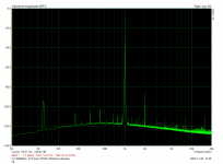
I have attached two FFT's. Of significance is how much lower the 60hz spur and its multiples are in V9 vs V8.
Great job Rod! Thank you!
Nash
I finally got around to updating to Rod's latest V9.
On my first listen to a violin concerto I felt that there was some kind of change in the presentation of the staging. Subsequently, I realized that the hall/venue appears larger than before, not that the musicians are sitting any farther apart, giving a much more realistic presentation.
Piano notes appeared to have more body and weight and there is a general increase in resolution throughout, without any sense of "showy detail". I noticed the improvement in timbre when listening to a wind quintet where I could more easily discern differences between the oboe and flute and the basoon and horn. Cello sounded better too. Orchestral works had more impact. I sense greater liquidity and ease in listening.
Overall, I am very pleased and pleasantly surprised by the improvement in sound.
I have attached two FFT's. Of significance is how much lower the 60hz spur and its multiples are in V9 vs V8.
Great job Rod! Thank you!
Nash
Attachments

- Home
- Amplifiers
- Tubes / Valves
- 01A question