I want to build a regulated 0.83 V power supply for the V ref pin of the TDA 1545 dac chip.
I am planning to use this
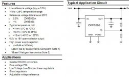
DIODES INC. - ZXRE060AET5TA - LINEAR REG, 0.6V, TSOT235
I need help to decide on the resistor value .
This is the link to the datasheet.
http://www.google.com.my/url?sa=t&s...prjgCw&usg=AFQjCNFPxVMlZOox7gVvIrdexN-HvwE7QA
Many thanks
kp93300
I am planning to use this
DIODES INC. - ZXRE060AET5TA - LINEAR REG, 0.6V, TSOT235
I need help to decide on the resistor value .
This is the link to the datasheet.
http://www.google.com.my/url?sa=t&s...prjgCw&usg=AFQjCNFPxVMlZOox7gVvIrdexN-HvwE7QA
Many thanks
kp93300
Attachments
This link is the application notes
http://www.google.com.my/url?sa=t&s...prjgCw&usg=AFQjCNGmq8tKPB18k0BYe_hHj3oNSaLcXw
http://www.google.com.my/url?sa=t&s...prjgCw&usg=AFQjCNGmq8tKPB18k0BYe_hHj3oNSaLcXw
Attachments
Just took a brief look at the TDA1545's datasheet. It appears to me that they use a ratiometric approach (Iref is a fraction of Vdd) to obtain appropriate bias currents and voltages. It also states that the optimum Vref value is Vdd*2/3, which is 3.33V at 5V supply.
I also see that PSRR is really bad with only 30dB. I would suggest to keep the ratiometric principle, maybe to buffer that Vdd*2/3 with an opamp, and to provide Vdd to the TDA1545 through a nice linear regulator.
I also see that PSRR is really bad with only 30dB. I would suggest to keep the ratiometric principle, maybe to buffer that Vdd*2/3 with an opamp, and to provide Vdd to the TDA1545 through a nice linear regulator.
Iref on TDA1545
Hi kp93300,
TDA1545 datasheet
quote:
R3 = R4 = 11k
Ifs=2mA
It seems this configuration reach optimum performance. In this case Vref@Iref = 1.6V.
Hi kp93300,
TDA1545 datasheet
quote:
R3 = R4 = 11k
Ifs=2mA
It seems this configuration reach optimum performance. In this case Vref@Iref = 1.6V.
@Eric: these values refer to the test condition for S/N. These are no working values, that are given on next page, I_FS = 0.9 ~ 1.1mA @ 5V. The application circuit uses R4=33k which should be kept as is. In this case Vref=3.3V @ 5V supply.
Hi tatus,
R3 = R4 = 11K is also used to measure THD.
from TDA1545 Datasheet, quote:
R3 = 22K, R4 = 33K, Ifs = 1mA
Total harmonic distortion at -60db 1.8% or 1.7% (depend of the page !)
Signal to noise ratio 98db
R3 = 11K, R4 = 11K, Ifs = 2mA
Total harmonic distortion at -60db 1.4%
Signal to noise ratio 101db
What does it mean exactly: Ifs might be pushed to 2mA for normal operation, or when Ifs=2mA the DAC outputs its max current?
Admit that Ifs=2mA max, best for measuring S/N (OK), but how do you measure THD? The DAC might clip if starting point is its full scale output! Did they perform a measure with -60db sinewave shifted to negative values to avoid clipping?
Last edited:
hi Eric and Tatus,
thanks for the input.
My knowledge is elementary
I have to go back to the drawing board to study the datasheets
kp93300
thanks for the input.
My knowledge is elementary
I have to go back to the drawing board to study the datasheets
kp93300
From TDA1545 datasheet, quote:
The reference output voltage Vref in Fig.1 is 2/3 Vdd. In this way the maximum dynamic range is achieved over the entire power supply range.
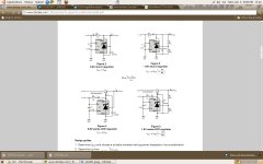
We can modeling TDA1545 with following schematic. IFS must be set to 1mA, tension at IREF pin is 0.83V.
The reference output voltage Vref in Fig.1 is 2/3 Vdd. In this way the maximum dynamic range is achieved over the entire power supply range.
We can modeling TDA1545 with following schematic. IFS must be set to 1mA, tension at IREF pin is 0.83V.
Attachments
From TDA1545 datasheet
quote:
The current IREF is proportional to VDD so the IFS and IBIAS will also be proportional to VDD (note 2) because AFS and Abias are constant.
In their schematic VREF is proportional to VDD. But, is there a good reason to keep IREF proportional to VDD since AFS(13.2) and Abias(9.42) are not equal? When IREF is proportional to VDD, any variations on VDD creates variations on Iout.
I think that kp93300 plan to use ZXRE060 only to generate 0.83 VREF tension, not to regulate TDA1545 +5V power supply....I also see that PSRR is really bad with only 30dB. I would suggest to keep the ratiometric principle, maybe to buffer that Vdd*2/3 with an opamp, and to provide Vdd to the TDA1545 through a nice linear regulator.
I agree the voltage at Iref input will be 0.83V. I was referring to the datasheet circuit where Vref is not the pin voltage itself. You can see that the bypass capacitor is not directly connected to the pin, there is a resistor inbetween. They will have good reason to have it that way. There are other posts in this forum suggesting to leave it as it is. As the PSRR of the TDA is very bad, I think a regulated 5V supply is mandatory anyway. One more point: the internal bias resistor has a very high tolerance. To compensate this, it should be fed with a 1.0mA current source and not with a 0.83V voltage source. That would an option to try in my opinion.
The reference current is converted into a voltage by the external opamps. This means the reference current sets the overall gain of the DAC, not only the offset. AC decoupling capacitors at the outputs are mandatory anyway in this design, so offset is not of that much importance. Just make sure the opamps do not leave their input/output specs.
To achieve good sonic performance, I would pay more attention to the opamps at the outputs. As they are operated as current-to-voltage converters, stability issues can easily occur.
Hi tatus,
R3 = R4 = 11K is also used to measure THD.
from TDA1545 Datasheet, quote:
R3 = 22K, R4 = 33K, Ifs = 1mA
Total harmonic distortion at -60db 1.8% or 1.7% (depend of the page !)
Signal to noise ratio 98db
R3 = 11K, R4 = 11K, Ifs = 2mA
Total harmonic distortion at -60db 1.4%
Signal to noise ratio 101db
What does it mean exactly: Ifs might be pushed to 2mA for normal operation, or when Ifs=2mA the DAC outputs its max current?
Admit that Ifs=2mA max, best for measuring S/N (OK), but how do you measure THD? The DAC might clip if starting point is its full scale output! Did they perform a measure with -60db sinewave shifted to negative values to avoid clipping?
The problem is that any values given in the "test condition" column are not usable in a design. You must keep your design within the specified limits. And that is Ifs = 0.9mA to 1.1mA. Don't know what the responsible engineers at Philips intended, maybe to pimp marketing figures? 🙂
Yes, necessary....As the PSRR of the TDA is very bad, I think a regulated 5V supply is mandatory anyway...
Hum, it might be interesting to know this reason. This capacitor is filtering hf noise coming from PSU and small current that might come from AOP. It drives AOP pin with necessary low impedance. Why not putting another small capacitor 10nF or 100nF directly to the IREF pin?...You can see that the bypass capacitor is not directly connected to the pin, there is a resistor inbetween. They will have good reason to have it that way. There are other posts in this forum suggesting to leave it as it is...
Yes, some post suggest to leave it as it is and other suggest to drive with 0.8V regulator 🙄
I think that results depends on how you drive this crucial pin. A noisy regulator might destroy global results. Because of its noise, I don't think that an integrated regulator might be used to directly drive this pin.
When driving IREF pin by voltage regulator, value of RREF (internal bias resistor) is not important.
What do you mean, IREF is only 76µA?One more point: the internal bias resistor has a very high tolerance. To compensate this, it should be fed with a 1.0mA current source and not with a 0.83V voltage source. That would an option to try in my opinion.
Last edited:
I think that kp93300 plan to use ZXRE060 only to generate 0.83 VREF tension, not to regulate TDA1545 +5V power supply.
This is correct.
thanks Eric.
kp93300
it might be interesting to know this reason. This capacitor is filtering hf noise coming from PSU and small current that might come from AOP. It drives AOP pin with necessary low impedance. Why not putting another small capacitor 10nF or 100nF directly to the IREF pin? ... some post suggest to leave it as it is and other suggest to drive with 0.8V regulator 🙄
I see it the same way. Probably worth to give both options a try, and let the ear (or an analyzer) judge.
When driving IREF pin by voltage regulator, value of RREF (internal bias resistor) is not important.
I disagree at this point. The reference current flowing into Iref pin sets gain, biases, etc. This current is the voltage at the pin divided by the internal resistor value. When any of the two change, then everything changes. By adding an external (precise) resistor in series, they actually reduce the effective tolerance, because then Iref = Vref / (Rref + 33k). With Rref = 7.4 ~ 14.6k (corresponding to +-33%), you get Iref = 70 ~ 82uA. This gives a tolerance of +-7.9%. Otherwise nobody would be able to reach the target spec of Isw= 1.0mA +-10%. For that reason I suggested using a precise (and of course low noise) current source for this pin. This will achieve precise gain and offsets. However it is not easy to create a current source that has similar noise performance as a resistor (maybe another reason for their choice in the datasheet).
What do you mean, IREF is only 76µA?
Bummer... you're right, 76uA is of course correct, I mixed up Iref and Ifs.
TDA1545A and Iref pin
Hello tatus,
Among forums, there is a lot of posts talking about IREF pin; nothing is very clear.
Is RREF a real resistor or an assembly of transistors and diodes?
Datasheet is not very clear too. IREF is illustrated in calibration principle. IREF for calibration and IREF at IREF pin don't seem to be the same: proportional, but not the same.
Sum of IREF for calibration might be equal to IFS max (2x2mA), while IREF at IREF pin is only 76uA...
I have some TDA1545A in my stock. I put a multimeter between pin 7 (IREF) and pin 4 (GND). There is a real resistor inside TDA1545A, RREF is a real resistor.
Last edited:
The Iref pin should be the input to multiple current mirror/multiplier stages (Ibias, Ibl, Ibr, probably even more internally). If I were the designer of that chip I would do this using current mirrors referenced to ground. The Rref drawn in the block diagram would then actually be a polysilicon resistor, not connected to gnd but connected to the input of that current mirror.
Anyhow, I would not integrate this resistor as this naturally causes it to have high production spread and temperature coefficient. An external resistor will do the job much better, but would increase component count that marketeers generally don't like ;-)
That Iref drawn in the calibration is actually a copy of Iref using that current mirrors. It is not the very same current, it cannot be. It is referenced to Vcc.
The idea behind that current mirror technique is that, with integrated circuits, it is very difficulty to create precise absolute references (volts, amperes, ohms). This typically requires chip internal calibration methods like laser trimming, eeprom, fusing, plus complex temperature compensation. For discrete designs, you often don't even need to think about it - IC design is more or less all around that. But what can be done very well is to create ratios (or factors). So the trick that they do here is take an external reference (that Iref current), and multiply it with a certain value. For a current mirror, the current ratio is given by the relation between the channel widths (for mos transistor based designs). That is purely geometric and can be reproduced quite well.
In other words: this device needs a stable and precise current flowing into that Iref pin for optimum performance and stability.
TDA1545A, direct driving Iref pin
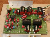
I'm testing my prototype of Jundac Five DAC using TDA1545. I think that the TDA1545 is able to very good audio rendering. For this kit, I set a fine environment with large power supplies using big MKP capacitors...
IREF configuration
Step 1
I try for various configurations for IREF pin. I start with datasheet recommendations. I reach the well known sound coming from TDA154: very sweet, not very detailed and (too) much rounded bass.
Step 2
The second step was to put a 10nF Wima FKP2 polypropylene film capacitor directly on the IREF pin. This improve sound rendering by adding more details and bass realism.
Step 3
The third step was to try various values for R2 and R3 and reducing serial resistor value of the IREF pin. This step improves sound rendering too.
Step 4
For this last step, I drive IREF pin by personal reference tension with very low impedance. With this configuration, I reach the real sound of TDA1545. Nothing matter with original one! In this configuration, TDA1545 keep a sweet tonal balance, natural and detailed sound and punchy bass.
Technical details
- I supply the TDA1545 with +5V6.
- Reference tension drives IREF pin by voltage with very low output impedance.
- Even in this configuration, there is a lot of disparity between various TDA1545A. Reference tension must include a pot to adjust output voltage.
- Since step 1 to step 4, I was totally out of Datasheet specs. Sometime under, sometime other!
- TDA1545 outputs +/-1.5mA. It is able to output more before clipping.
Conclusion
The global sound rendering of TDA1545A depends on how you drive the IREF pin. Driving IREF with voltage reference with very low output impedance greatly improve listening results. The datasheet is not very clear; the TDA1545A is able to better specs. With optimum configuration, TDA1545 is a great DAC chip.
Attachments
Last edited:
- Status
- Not open for further replies.
- Home
- Amplifiers
- Power Supplies
- 0.83V regulated supply