This is my first diyAudio post about my recent design and build of quirky loudspeakers. See my recent introduction for brief background about me.
This will need to be an extensive story to give you the full picture of my project. Feel free to jump to the section you're interested in.
I designed and build two versions of this kind of subwoofer, and this post will be about the second version, hence the "version 2" in the title. A post about the smaller "version 1" might come later.

Background
This idea of mine was born out of the last dull, depressing darkness of the Swedish winter. It has been 20+ years since I build a decent loudspeaker on my own, and suddenly this passion came washing over me again. It probably started when my now retired Harman Kardon active speakers started failing, and after trying to repair and revive them simply gave up. Suddenly I was without quality sound in my 88 m² apartment and my restless engineering brain started humming in 200 radians per second to find a solution. 🙃
I just recently found SoundImports EU (apparently the "Parts Express" of Europe!?), which offers an impressive DIY assortment for appealing prices, and ships fast and cheap to my area. I needed a subwoofer, and spontaneously bought the Dayton Audio 6-1/2" Down Firing subwoofer kit, thinking the specs looked to fulfil the needs of my living, fair price, and the box build (well, assembly of pre-cut boards) will be simple and quick. The subwoofer kit was most of that; it makes a lot of low-end noise for being a 6.5" driver. But my ears were not satisfied! So I started researching some more exotic subwoofer builds. I needed a design that would stimulate not only my ears, but also my brain cells during design, and also something different to satisfy my need for novelty.
My prior background in PA-loudspeakers makes my judgement biased; Long time ago I owned setups of 15" bass-reflex, 15" folded horns and 2x18" (pseudo)-horns to cover the low-end of my sound rigs. And those were driven by 19" rack professional amplifiers with power ratings in the kilowatt area. I loved the deep rumbling and physical sensations this setup could produce.
Reality check: I now own and live in an apartment in a multi-tenant house. Even if I would fit a 15-18" subwoofer at home, my skewed audio taste would probably get me evicted or at least throw my reputation among neighbors down the basement. So, I needed to let go of my comfort area: PA-class woofers, but I wanted most of the features they could offer!
Subwoofer requirements
Trying to list what I was aiming for in terms of end results
During my research (well, watching YouTube, visiting many obscure audio pages seemingly designed in the 90's, and scrolling through this excellent forum), I was captivated by two main categories for a custom speaker design, listed here with my conclusions and pros/cons:
Engineering design
I decided to use a quarter-wave transmission-line enclosure, based entirely on standard pipe fittings! Because in theory it is supposed to work just great, AND just the idea of it sound ridiculous. That's just what I was looking for!
I read numerous guides and theory for transmission line enclosures (hereafter: TL), e.g: quarter-wave, diysubwoofers.
I learned quickly that Hornresp is a great tool to use for evaluating potential designs (my deepest gratitude to the Hornresp team for offering this great piece of software!).
SpicyTL is another very promising software, but haven't come to terms with those libraries quite yet, despite being based on the SPICE software, which I'm previously familiar with.
How big?
The high-level design of a TL subwoofer enclosure starts with two parameters: Lowest resonance frequency and mouth air speed at max intended SPL. The former is easy to approximate: "Quarter wave" means that one-quarter of the longest wave needs to fit inside the line. Deep sub-bass down to 20 Hz would be lovely, but 343 m/s / 20 Hz / 4 = 4.3 m, which would be inconvenient to squeeze into my apartment with 2.5 m ceiling height without folding (complicated build). What about setting the max line length to 2.5 m then, as in using my full height of the ceiling walls? 343 m/s / 2.5 m / 4 = 34.3 Hz. Well, this is not too bad, considering I just saved one 180° fold and 1.8 meters of piping! Regardless of the TL lowest resonance frequency, the selected driver needs to be able to work properly at these levels.
The air speed at the line mouth is important because high air velocities will cause turbulence at high sound levels, which might create huffing, puffing and whining sounds, or just simply "chuffing". Carefully designing the mouth geometry could alleviate much of this problem, but in my case, I will need to accept the shape and geometry of standard pipes! I assumed a guesstimate of 10-15 m/s for maximum air speed at the mouth. Knowing this number makes it easy to calculate a suitable diameter for the TL. I made some simple estimations by calculating the maximum volumetric air flow at the mouth (cross-section area * max air speed), and comparing that to what a suitable driver would be able to generate, given by TS-parameters Xmax * Sd (with care taken to unit conversions).
Off-the-shelf piping comes in highly standardized diameters. I browsed through dozens of product catalogs of both plastic, paper and metal pipes from my local hardware stores, and decided to go with large plastic pipes. The relevant sizes for a sub-woofer that I could easily buy are (outer) diameters 110 mm or 160 mm. This types of plastic pipes are normally used to carry sewage water inside- and between buildings. This makes a great excuse is the designs turns out to sound like ****! 🤪
I decided quickly that I wanted to build a TL without any need for an additional "throat chamber" made as a typical rectangular box (again, no wood, please!). This is a key difference from the inspiration I got from the typical El Pipe-O subwoofers. Basic design rule: Use only standard pipe fittings!
The next challenge I encountered is that a simple straight line made with smooth, hard linings will sound like an echo chamber. Therefore, careful consideration must be put into the type and amount of damping. Thankfully, Hornresp allowed me to evaluate both placing, properties and amount of damping material through simulations. More about the outcome later.
Driver requirements
From the TL-design sources mentioned above, I read that suitable drivers for TL enclosures, in terms of TS-parameters would need a low Fs (quite obvious for a subwoofer design!?), but even more importantly, low Qts (effectively meaning low Qes!?). Attention to the risk of over-excursion is important with low-Qts drivers. This might, or might not, be a problem in a TL design.
I made a list... well many lists, of potential drivers to use in my design. I didn't want to spend a fortune, in case this experiment failed. But I still wanted a great fit in characteristics (TS-parameters) for a TL. As a surprise, the very same driver included in the budget subwoofer kit I first bought from SoundImports (DCS165-4) turned out as the best budget alternative driver for a TL-design, thanks to its reasonably low Qts of 0.34!
Here's a list of my four favorite drive candidates:
The selection of driver is made not only on the TS-parameters, price and availability, but also on geometric details like exact baffle size. Since I am basing my entire enclosure on standard pipes, I really want to maximize the cone area able to fit onto or into a standardized pipe! I would not allow valuable millimeters get wasted by a sloppy mechanical fit! Many driver candidates got rejected on the simple basis that their data sheets did NOT include precise measurements of the baffle, mounting holes or cutout diameter!
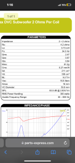
The selected "Ultimax UM8-22 Subwoofer" is a pretty sturdy piece of driver at 6.9 kg, dual 2", 2 Ohm voice coils and ±16 mm of linear excursion and specified at 300 W rms power!


As soon as I got my driver delivered, I measured its TS-parameters using a DATS V3. Maybe not surprising, but the TS-parameters were deviating from the datasheet. This would probably mean that the TS system will not behave as simulated. But taking this into account in the design process is one variable to much to handle right now. And in best of cases, the actual TS-parameters will stabilize close to the datasheet values after some "burn-in" of the driver.
Transmission Line Layout
A long straight line at ~2.5 m, and enough diameter to support the maximum air flow of the driver. Sound simple!
But... I learned through simulations that a straight TL design without any tricks will have a quite narrow bandwidth in frequency. For a design reaching just below 30 Hz (±3 dB), a destructive interference pattern would show up at 90 Hz (basically 3 * lowest resonance), and severely reducing the sound pressure output near this upper range.
I found a trick, which is to mount the driver "offset" along the TL. According to theory, and simulations, this will alleviate the first order of destructive interference patterns in the frequency range. I experimented a lot through Hornresp simulations, with the rule of thumb that a good driver offset seem to be 1/3 of the full TL length away from the closed-end.
This trick does not only produce a very appealing frequency response, but it also opens up for a few more positive design options (which "version 1" does not have):
Hornresp layout:


The UM8-22 driver has a baffle cut-out of 189 mm (according to drawing), which is obviously too large to fit in a 160 mm pipe. Hence, an adaptor is needed. After scrolling through many products of sewage pipes, I found a standar component named "chamber rodding tee", which is available as 160 mm diameter for the main line, and 200 mm for the inspection inlet. The UM8-22 driver fits perfectly into the take-out section with only "minimal" changes to the plastic structure. The rodding tee pipe comes only in the color Obnoxious Orange, so I spent some time learning how to paint Polypropylene plastic.

The main TL is constructed out of "premium" drainage pipes from Geberit: Silent-PP. I picked these pipes mainly because of the aesthetics (available in black), but almost ironically, these pipes are intended for "sound-optimised installation of drainage systems" 😄 What it actually means is that the wall thickness is higher than the pipe standard requires, which increases the stiffness of the pipe, and hence reduces resonances in a typical drainage installation.
Simulation results
Hornresp results are presented assuming eight space radiation. Datasheet TS-params are used for UM8-22.
Acoustic output at 1 W (left graph), and max power 300 W (right graph). Sections of bold red means excursion-limited output.


Group delay (left graph). Mouth air speed at 300 W (right graph).


End results
So far, this unit has been in operation for a few months in my apartment. It plays LOUD and DEEP! Probably generating slight annoyance in my neighbors, but I'm till not evicted 😄.
It is currently hooked up with the dual 2 Ohm voice coils in series and powered by a tiny 100 W class-D amplifier, which is capable of generating more rumbling than I dare to continuously play in a multi-tenant house.
I do realize that my living room most likely has strong constructive resonances around the lower end of the pipe-sub's frequency range, which might make it sound more impressive than it might be in a resonant-free environment. Though, I recently took my "pipe-sub v2" (also known as "Bazooka-sub", or "Super-Mario-Woofer") to a workshop and hooked up to a more capable amplifier to test it's capability in a bigger room, and an environment where people wouldn't mind some loud noises. I can only say it did not fail to surprise me, as it continued to played deep and loud with linear excursion (and surprisingly low amounts of chuffing and/or air leakage) for as long as the amplifier's power supply could support us.
Super-mario-woofer!?

Full-size image of end result:

I'm looking forward to your feedback on this project!
This will need to be an extensive story to give you the full picture of my project. Feel free to jump to the section you're interested in.
I designed and build two versions of this kind of subwoofer, and this post will be about the second version, hence the "version 2" in the title. A post about the smaller "version 1" might come later.
Background
This idea of mine was born out of the last dull, depressing darkness of the Swedish winter. It has been 20+ years since I build a decent loudspeaker on my own, and suddenly this passion came washing over me again. It probably started when my now retired Harman Kardon active speakers started failing, and after trying to repair and revive them simply gave up. Suddenly I was without quality sound in my 88 m² apartment and my restless engineering brain started humming in 200 radians per second to find a solution. 🙃
I just recently found SoundImports EU (apparently the "Parts Express" of Europe!?), which offers an impressive DIY assortment for appealing prices, and ships fast and cheap to my area. I needed a subwoofer, and spontaneously bought the Dayton Audio 6-1/2" Down Firing subwoofer kit, thinking the specs looked to fulfil the needs of my living, fair price, and the box build (well, assembly of pre-cut boards) will be simple and quick. The subwoofer kit was most of that; it makes a lot of low-end noise for being a 6.5" driver. But my ears were not satisfied! So I started researching some more exotic subwoofer builds. I needed a design that would stimulate not only my ears, but also my brain cells during design, and also something different to satisfy my need for novelty.
My prior background in PA-loudspeakers makes my judgement biased; Long time ago I owned setups of 15" bass-reflex, 15" folded horns and 2x18" (pseudo)-horns to cover the low-end of my sound rigs. And those were driven by 19" rack professional amplifiers with power ratings in the kilowatt area. I loved the deep rumbling and physical sensations this setup could produce.
Reality check: I now own and live in an apartment in a multi-tenant house. Even if I would fit a 15-18" subwoofer at home, my skewed audio taste would probably get me evicted or at least throw my reputation among neighbors down the basement. So, I needed to let go of my comfort area: PA-class woofers, but I wanted most of the features they could offer!
Subwoofer requirements
Trying to list what I was aiming for in terms of end results
- Great low-end, sub-woofer response:
- Flat and loud subwoofer response, say 30-100 Hz ±3 dB.
- Decent phase response or group delay within the target frequency range.
- Apartment-friendly, semi-portable design (I need to move it in and out of my 3rd floor apartment on my own).
- High acoustic efficiency (avoid the need of another kW amplifier).
- I want to be able to do all engineering design by myself, using free or easily available tools/software.
- The design needs to be quirky/novel/different to satisfy my restless engineering mind.
- Assembly of the final speaker needs to be relatively clean and un-complicated:
- I'd like to do all work in my apartment and/or electronics lab.
- Avoid using wood as building material, as cutting it is too dirty for my facilities.
During my research (well, watching YouTube, visiting many obscure audio pages seemingly designed in the 90's, and scrolling through this excellent forum), I was captivated by two main categories for a custom speaker design, listed here with my conclusions and pros/cons:
- 6th order, dual reflex, triple-chamber parallel bandpass with small (5-8") drivers:
- Plus (quirky): This is not a very common design!?
- Using three different tuning frequencies to offer a wide frequency response:
- Design with all three chambers tuned differently (the default design would have two identical chambers, I assume).
- Plus (novelty): I never found anyone publishing a 6thr order enclosure with three intentionally different tuning frequencies!
- Design with two different drivers in the same dual-chamber design to achieve wider frequency response and/or better group delay.
- Plus (novelty): Also never found this solution online!
- Design with all three chambers tuned differently (the default design would have two identical chambers, I assume).
- Using small drivers would allow for a low-height rectangular cuboid that I could possibly hide under a sofa or other furniture.
- Minus (build): The box will be a regular box that is best built using wooden panels.
- Inspiration:
- Horn-loaded designs
- Front-loaded folded horn
- Plus: Ticks most boxes for acoustic performance.
- Minus (novelty): I owned them before, quite common woofer design.
- Tapped horn
- Inspiration: HexiBase: 4" tapped horn with laser-cut wood panels
- Plus (novelty): Uncommon for being a horn-design!
- Minus (build): Best built with wooden panels, but I could potentially outsource the cutting in a laminated design
- 3D-printed horn-hybrid / wave guide
- Inspiration: HexiBase 3D printed folded wave guide 3" subwoofer
- Cool stuff, but I don't own a 3D printer, and acquiring one would just throw me into another rabbit hole of endless distractions
- Quarter-wave transmission line
- Transmission lines are basically straight-line horn designs, I learned.
- Minus (novelty): Common layout in some high-end, full-range speakers.
- Minus (build): Usually built with wood panels as square boxes.
- Non-rectangular cuboid transmission lines:
- Inspiration:
- AudioJudgement: Pipe Speakers with dual 2.5" drivers
- I actually built a version of these speakers too, more about that in another post.
- El Pipe-O subwoofers
- AudioJudgement: Pipe Speakers with dual 2.5" drivers
- Wait WHAT!? Standard pipe fittings can make a good transmission line enclosure!?
- What if it scaled up...? Hold my beer... (all boxes ticked)! 🤩
- Inspiration:
- Front-loaded folded horn
Engineering design
I decided to use a quarter-wave transmission-line enclosure, based entirely on standard pipe fittings! Because in theory it is supposed to work just great, AND just the idea of it sound ridiculous. That's just what I was looking for!
I read numerous guides and theory for transmission line enclosures (hereafter: TL), e.g: quarter-wave, diysubwoofers.
I learned quickly that Hornresp is a great tool to use for evaluating potential designs (my deepest gratitude to the Hornresp team for offering this great piece of software!).
SpicyTL is another very promising software, but haven't come to terms with those libraries quite yet, despite being based on the SPICE software, which I'm previously familiar with.
How big?
The high-level design of a TL subwoofer enclosure starts with two parameters: Lowest resonance frequency and mouth air speed at max intended SPL. The former is easy to approximate: "Quarter wave" means that one-quarter of the longest wave needs to fit inside the line. Deep sub-bass down to 20 Hz would be lovely, but 343 m/s / 20 Hz / 4 = 4.3 m, which would be inconvenient to squeeze into my apartment with 2.5 m ceiling height without folding (complicated build). What about setting the max line length to 2.5 m then, as in using my full height of the ceiling walls? 343 m/s / 2.5 m / 4 = 34.3 Hz. Well, this is not too bad, considering I just saved one 180° fold and 1.8 meters of piping! Regardless of the TL lowest resonance frequency, the selected driver needs to be able to work properly at these levels.
The air speed at the line mouth is important because high air velocities will cause turbulence at high sound levels, which might create huffing, puffing and whining sounds, or just simply "chuffing". Carefully designing the mouth geometry could alleviate much of this problem, but in my case, I will need to accept the shape and geometry of standard pipes! I assumed a guesstimate of 10-15 m/s for maximum air speed at the mouth. Knowing this number makes it easy to calculate a suitable diameter for the TL. I made some simple estimations by calculating the maximum volumetric air flow at the mouth (cross-section area * max air speed), and comparing that to what a suitable driver would be able to generate, given by TS-parameters Xmax * Sd (with care taken to unit conversions).
Off-the-shelf piping comes in highly standardized diameters. I browsed through dozens of product catalogs of both plastic, paper and metal pipes from my local hardware stores, and decided to go with large plastic pipes. The relevant sizes for a sub-woofer that I could easily buy are (outer) diameters 110 mm or 160 mm. This types of plastic pipes are normally used to carry sewage water inside- and between buildings. This makes a great excuse is the designs turns out to sound like ****! 🤪
I decided quickly that I wanted to build a TL without any need for an additional "throat chamber" made as a typical rectangular box (again, no wood, please!). This is a key difference from the inspiration I got from the typical El Pipe-O subwoofers. Basic design rule: Use only standard pipe fittings!
The next challenge I encountered is that a simple straight line made with smooth, hard linings will sound like an echo chamber. Therefore, careful consideration must be put into the type and amount of damping. Thankfully, Hornresp allowed me to evaluate both placing, properties and amount of damping material through simulations. More about the outcome later.
Driver requirements
From the TL-design sources mentioned above, I read that suitable drivers for TL enclosures, in terms of TS-parameters would need a low Fs (quite obvious for a subwoofer design!?), but even more importantly, low Qts (effectively meaning low Qes!?). Attention to the risk of over-excursion is important with low-Qts drivers. This might, or might not, be a problem in a TL design.
I made a list... well many lists, of potential drivers to use in my design. I didn't want to spend a fortune, in case this experiment failed. But I still wanted a great fit in characteristics (TS-parameters) for a TL. As a surprise, the very same driver included in the budget subwoofer kit I first bought from SoundImports (DCS165-4) turned out as the best budget alternative driver for a TL-design, thanks to its reasonably low Qts of 0.34!
Here's a list of my four favorite drive candidates:
- Dayton Audio DCS165-4 - 6.5"
- SEAS CD22RN4X - H1192 - 8"
- Dayton Audio UM8-22 - 8"
- Dayton Audio UMII8-22 - 8"
The selection of driver is made not only on the TS-parameters, price and availability, but also on geometric details like exact baffle size. Since I am basing my entire enclosure on standard pipes, I really want to maximize the cone area able to fit onto or into a standardized pipe! I would not allow valuable millimeters get wasted by a sloppy mechanical fit! Many driver candidates got rejected on the simple basis that their data sheets did NOT include precise measurements of the baffle, mounting holes or cutout diameter!
The selected "Ultimax UM8-22 Subwoofer" is a pretty sturdy piece of driver at 6.9 kg, dual 2", 2 Ohm voice coils and ±16 mm of linear excursion and specified at 300 W rms power!
As soon as I got my driver delivered, I measured its TS-parameters using a DATS V3. Maybe not surprising, but the TS-parameters were deviating from the datasheet. This would probably mean that the TS system will not behave as simulated. But taking this into account in the design process is one variable to much to handle right now. And in best of cases, the actual TS-parameters will stabilize close to the datasheet values after some "burn-in" of the driver.
Transmission Line Layout
A long straight line at ~2.5 m, and enough diameter to support the maximum air flow of the driver. Sound simple!
But... I learned through simulations that a straight TL design without any tricks will have a quite narrow bandwidth in frequency. For a design reaching just below 30 Hz (±3 dB), a destructive interference pattern would show up at 90 Hz (basically 3 * lowest resonance), and severely reducing the sound pressure output near this upper range.
I found a trick, which is to mount the driver "offset" along the TL. According to theory, and simulations, this will alleviate the first order of destructive interference patterns in the frequency range. I experimented a lot through Hornresp simulations, with the rule of thumb that a good driver offset seem to be 1/3 of the full TL length away from the closed-end.
This trick does not only produce a very appealing frequency response, but it also opens up for a few more positive design options (which "version 1" does not have):
- The driver does not need to be mounted on the closed-end of the TL
- The TL closed-end can rest directly on the floor
- No need for protection or vertical offset of the TL to allow the driver cone coming close to the floor
- This effectively saves about 200 mm of dead vertical space, which can be used for the main TL length instead. Great when the vertical space is the limiting factor for the design!
- The driver can instead be mounted facing outwards, which is (in my opinion) esthetically preferable.
- The TL closed-end can rest directly on the floor
Hornresp layout:
The UM8-22 driver has a baffle cut-out of 189 mm (according to drawing), which is obviously too large to fit in a 160 mm pipe. Hence, an adaptor is needed. After scrolling through many products of sewage pipes, I found a standar component named "chamber rodding tee", which is available as 160 mm diameter for the main line, and 200 mm for the inspection inlet. The UM8-22 driver fits perfectly into the take-out section with only "minimal" changes to the plastic structure. The rodding tee pipe comes only in the color Obnoxious Orange, so I spent some time learning how to paint Polypropylene plastic.
The main TL is constructed out of "premium" drainage pipes from Geberit: Silent-PP. I picked these pipes mainly because of the aesthetics (available in black), but almost ironically, these pipes are intended for "sound-optimised installation of drainage systems" 😄 What it actually means is that the wall thickness is higher than the pipe standard requires, which increases the stiffness of the pipe, and hence reduces resonances in a typical drainage installation.
Simulation results
Hornresp results are presented assuming eight space radiation. Datasheet TS-params are used for UM8-22.
Acoustic output at 1 W (left graph), and max power 300 W (right graph). Sections of bold red means excursion-limited output.
Group delay (left graph). Mouth air speed at 300 W (right graph).
End results
So far, this unit has been in operation for a few months in my apartment. It plays LOUD and DEEP! Probably generating slight annoyance in my neighbors, but I'm till not evicted 😄.
It is currently hooked up with the dual 2 Ohm voice coils in series and powered by a tiny 100 W class-D amplifier, which is capable of generating more rumbling than I dare to continuously play in a multi-tenant house.
I do realize that my living room most likely has strong constructive resonances around the lower end of the pipe-sub's frequency range, which might make it sound more impressive than it might be in a resonant-free environment. Though, I recently took my "pipe-sub v2" (also known as "Bazooka-sub", or "Super-Mario-Woofer") to a workshop and hooked up to a more capable amplifier to test it's capability in a bigger room, and an environment where people wouldn't mind some loud noises. I can only say it did not fail to surprise me, as it continued to played deep and loud with linear excursion (and surprisingly low amounts of chuffing and/or air leakage) for as long as the amplifier's power supply could support us.
Super-mario-woofer!?
Full-size image of end result:
I'm looking forward to your feedback on this project!

Ahh, sweet @Booger weldz , having access to free "spare pipes" would have helped me in my development. It took me a few months of experiments with smaller setups before I was ready to pursue the "version 2" with premium components.
I bought the pipes in 0.5 m lengths primarily because they could be shipped from an online store with regular freight. None of the premium pipes I found appealing for this build were available in any of my hardware stores.
Rough budget for my build (1 EUR = 1 USD at the time of build):
I bought the pipes in 0.5 m lengths primarily because they could be shipped from an online store with regular freight. None of the premium pipes I found appealing for this build were available in any of my hardware stores.
Rough budget for my build (1 EUR = 1 USD at the time of build):
- 1 * Driver UM8-22: 182 EUR
- 3 * Geberit SilentPro pipe 160 mm x 500 mm: 120 EUR
- 1 * Geberit end-cap 160 mm: 12 EUR
- 1 * 160-200 mm chamber rodding tee: 70 EUR
- 2 * Spray primer for plastics: 14 EUR
- 2 * Spray paint black: 20 EUR
- Misc. screws, terminals, glue, seals: 20 EUR
More build pictures!
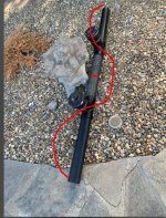
The Chamber Rodding Tee (or "cleaning access pipe") that acted as my 200-to-160 mm adapter was cut down to avoid excessive horizontal overhang since I wanted the full-length TL to be able to stand vertically on its own.
Left: Original product. Right: After first cut with jigsaw


Left: Will driver fit? Drawing measures indicates probably.
Right: The original rim from the rodding tee was also cut off and re-used to act as a sleeve.


Yes! With the extra sleeve glued back on, the UM8-22 fits perfectly in the 200 mm pipe opening!
With this adapter, the standard 160 mm pipes can easily be attached on either end of the chamber rodding tee.

The Chamber Rodding Tee (or "cleaning access pipe") that acted as my 200-to-160 mm adapter was cut down to avoid excessive horizontal overhang since I wanted the full-length TL to be able to stand vertically on its own.
Left: Original product. Right: After first cut with jigsaw
Left: Will driver fit? Drawing measures indicates probably.
Right: The original rim from the rodding tee was also cut off and re-used to act as a sleeve.
Yes! With the extra sleeve glued back on, the UM8-22 fits perfectly in the 200 mm pipe opening!
With this adapter, the standard 160 mm pipes can easily be attached on either end of the chamber rodding tee.
Will this work, at all?
I did a preliminary assembly and hooked it up to my DATSv3 impedance sweeper, and then to an audio amplifier.


Now this is only 2.0 meters of the intended 2.3-2.5 meters, so not expecting full performance.
But I could easily modify the Hornresp design to this shorter TL length, remove stuffing in simulations, and compare the simulated impedance vs measurements.
Left graph: Impedance measurement with DATSv3 for 2.0 m prototype assembly. Z_min = 39.7 Hz
Right graph: Hornresp impedance simulation with 2.0 m undamped TL (red), and target design in grey (ca 2.3 m, with damping). Z_min = 32.8 Hz


Hornresp frequency response at 1 W. Red curve: 2.0 m undamped TL. Gray: Target 2.3 m design with damping.
Just as expected, removing 0.3-0.5 m from the total TL length will severely impact the bottom-end response.
The implications of not having any damping is clearly seen in the Hornresp response in the spiky red curve. Hornresp manages to capture the echoes in a straight pipes without damping, which in real life sounds terrible!

Measurements and simulations seemed to match fairly well. One source of discrepancy was that the measured TS-parameters for the UM8-22 driver were deviating compared to the datasheet values I'm using in Hornresp. This discrepancy will hopefully shrink during driver burn-in.
I did a preliminary assembly and hooked it up to my DATSv3 impedance sweeper, and then to an audio amplifier.
Now this is only 2.0 meters of the intended 2.3-2.5 meters, so not expecting full performance.
But I could easily modify the Hornresp design to this shorter TL length, remove stuffing in simulations, and compare the simulated impedance vs measurements.
Left graph: Impedance measurement with DATSv3 for 2.0 m prototype assembly. Z_min = 39.7 Hz
Right graph: Hornresp impedance simulation with 2.0 m undamped TL (red), and target design in grey (ca 2.3 m, with damping). Z_min = 32.8 Hz
Hornresp frequency response at 1 W. Red curve: 2.0 m undamped TL. Gray: Target 2.3 m design with damping.
Just as expected, removing 0.3-0.5 m from the total TL length will severely impact the bottom-end response.
The implications of not having any damping is clearly seen in the Hornresp response in the spiky red curve. Hornresp manages to capture the echoes in a straight pipes without damping, which in real life sounds terrible!
Measurements and simulations seemed to match fairly well. One source of discrepancy was that the measured TS-parameters for the UM8-22 driver were deviating compared to the datasheet values I'm using in Hornresp. This discrepancy will hopefully shrink during driver burn-in.
Painting of chamber rodding tee
I simply cannot stand this Obnoxious Orange, which is the standard color for outdoor piping.
Pipes are made out of Polypropylene, which is know to be a challenge to paint properly.
Left picture: I first sanded down the worst manufacturing defects, dents and scratches.
Right picture: Then flamed the surface with a torch to expel the paint-repelling solvents from the surface of the plastic.


Then spray painted with several layers of primer.
And several layers of black spray paint.
Thanks to my brother who let me use his workshop, including this extra ventilated paint cabinet.


After a few hours of painting, including preparations. It's not perfect, but good enough for my first serious paint using Polypropylene drainage pipes 😄

Ready for assembly!
I fitted some high-quality foam sealing to prevent air leakage between driver and rodding tee.

I simply cannot stand this Obnoxious Orange, which is the standard color for outdoor piping.
Pipes are made out of Polypropylene, which is know to be a challenge to paint properly.
Left picture: I first sanded down the worst manufacturing defects, dents and scratches.
Right picture: Then flamed the surface with a torch to expel the paint-repelling solvents from the surface of the plastic.
Then spray painted with several layers of primer.
And several layers of black spray paint.
Thanks to my brother who let me use his workshop, including this extra ventilated paint cabinet.
After a few hours of painting, including preparations. It's not perfect, but good enough for my first serious paint using Polypropylene drainage pipes 😄
Ready for assembly!
I fitted some high-quality foam sealing to prevent air leakage between driver and rodding tee.
Last edited:
Final assembly
The UM8-22 driver (still) fits perfectly!

I removed the rubber protection from the heavy-duty magnets before the end assembly. It will probably save some cm³ of TL volume and slightly decrease turbulence inside the pipe.
Binding posts
As the project was approaching the final stage, selection and installation of binding posts took a disproportional amount of time 🤷♂️
The driver features dual voice coils, and I wanted to route all connections to the outside. I want to use the default 4 mm "banana plug" terminal type, but avoiding that the terminals extend far out and receives damage when the TL gets transported or moved around. The rodding tea features some ribs on the back-side, which I figured will serve as a basic protection for the binding posts in terms of avoiding direct impact.
Left: What binding posts to select?
Middle: Holes drilled for binding posts. Again, Polypropylene is terrible to machine!
Right: All four binding posts successfully installed, and the dual 2 Ohm voice coils are series connected using an external jumper.


End results - close-ups
The driver is attached using short, black plated wooden screws directly into the rim-enhanced PP-pipe.


The UM8-22 driver (still) fits perfectly!
I removed the rubber protection from the heavy-duty magnets before the end assembly. It will probably save some cm³ of TL volume and slightly decrease turbulence inside the pipe.
Binding posts
As the project was approaching the final stage, selection and installation of binding posts took a disproportional amount of time 🤷♂️
The driver features dual voice coils, and I wanted to route all connections to the outside. I want to use the default 4 mm "banana plug" terminal type, but avoiding that the terminals extend far out and receives damage when the TL gets transported or moved around. The rodding tea features some ribs on the back-side, which I figured will serve as a basic protection for the binding posts in terms of avoiding direct impact.
Left: What binding posts to select?
Middle: Holes drilled for binding posts. Again, Polypropylene is terrible to machine!
Right: All four binding posts successfully installed, and the dual 2 Ohm voice coils are series connected using an external jumper.
End results - close-ups
The driver is attached using short, black plated wooden screws directly into the rim-enhanced PP-pipe.
Nice build! Basically, it's an offset-driver straight TL (which I describe on my TL page, https://www.diysubwoofers.org/tls/), which is great for subwoofer duty. I have a few examples of ODTLs on my website, though none of them were created using PVC pipe. Quite creative! Looks almost like a Steampunk-inspired design... It needs to be painted in brass and "aged" to complete the look 🙂.
I took a look at that transmission line subwoofer design for the PA-310-8. Although it has good low-frequency extension, it's concerning how many sharp transmission-line resonances are present. Wouldn't it be much simpler to go with a vented-box loudspeaker low-frequency alignment?
To investigate this idea a bit further, the simulation below shows the predicted results for the PA-310-8 driver in a Vb=110litre enclosure tuned to 30Hz. All that's been added is a simple shelf filter. It could be expected, could it not, that the port would introduce very low amplitude acoustic resonances when the subwoofer has been low-pass filtered by the typical 80Hz L–R low-pass filter, way lower than those in a TL enclosure, whose line needs to be extensively damped in a rather complex manner? This whole contraption seems a lot simpler to create with any DSP-capable plate amplifier. And we have an F3=27.5Hz, versus the F3 of around 48Hz in the TL system. It seems to me that moderately EQed vented-box systems offer a significantly better performing subwoofer with this particular driver, and no doubt many others.

Of course, as we need to control excessive cone motion at low-frequencies, we do need to seriously consider the application of a high-pass filter to our system. This knocks off a few Hz of low-frequency extension, but that's also going to be the case for TL systems (I've seen their decoupled cone motion in action first-hand). Below is a simulated potential system that includes a 2nd-order HP filter.
Note how the maximum vent velocity is nice and low.

How does this compare with a TL design using the same driver? Is it a viable result? Does it offer any benefits?
To investigate this idea a bit further, the simulation below shows the predicted results for the PA-310-8 driver in a Vb=110litre enclosure tuned to 30Hz. All that's been added is a simple shelf filter. It could be expected, could it not, that the port would introduce very low amplitude acoustic resonances when the subwoofer has been low-pass filtered by the typical 80Hz L–R low-pass filter, way lower than those in a TL enclosure, whose line needs to be extensively damped in a rather complex manner? This whole contraption seems a lot simpler to create with any DSP-capable plate amplifier. And we have an F3=27.5Hz, versus the F3 of around 48Hz in the TL system. It seems to me that moderately EQed vented-box systems offer a significantly better performing subwoofer with this particular driver, and no doubt many others.
Of course, as we need to control excessive cone motion at low-frequencies, we do need to seriously consider the application of a high-pass filter to our system. This knocks off a few Hz of low-frequency extension, but that's also going to be the case for TL systems (I've seen their decoupled cone motion in action first-hand). Below is a simulated potential system that includes a 2nd-order HP filter.
Note how the maximum vent velocity is nice and low.
How does this compare with a TL design using the same driver? Is it a viable result? Does it offer any benefits?
Last edited:
@witwald thanks, I'm interested in comparing my build to other alternatives.
For vented boxes, I'm concerned about the total volume needed for a low tuning, and the resulting group delay. Especially if aggressive signal filtering is needed, which will also introduce phase skew and group delay in the system.
Your driver, PA-310-8, seem to be a 12", which would be an apple-to-orange comparison with my 8" driver.
Even if my TL stands 2.3 meters tall, the actual enclosed volume is only about 60 liters. This was a surprise to me, that the TL volume does not to be much bigger than typical vented boxes. But the form factor is quite different, which I like.
Concerning the sharp ransmission-line resonances, I guess you are referring to the echoes and resonances within the pipe?
Yes, it's a problem. And I spend lots of time exploring this first in Hornresp, which models this i detail with both detailed position and density of the damping material. Then I did several experiments on 4-5 of my other recent TL builds (which I might show in future topics) to verify that simulations makes sense.
Running my LT without any stuffing inside sound terrible, I have tried it. But, it turns out that its rather simple to damp a straight line without losing low-end performance! After lots of experiments, I ended up with a very straight-forward damping layout, as shown in my first post in this thread:

The gray area of the TL cross-section means "stuffing". It corresponds to the bottom 40 cm being stuffed with 120 grams of suitable damping material. This will effectively eliminate all harmonics above the intended frequency range of ~30-100 Hz, but barely affect the low-end response. This makes sense, because the air speed in this end of the pipe for the lower frequencies is close to zero. The stuffing even increases the effective length of the pipe to some extent (because lower sound speed inside the damping material?), which makes the tuning frequency even lower!
For vented boxes, I'm concerned about the total volume needed for a low tuning, and the resulting group delay. Especially if aggressive signal filtering is needed, which will also introduce phase skew and group delay in the system.
Your driver, PA-310-8, seem to be a 12", which would be an apple-to-orange comparison with my 8" driver.
Even if my TL stands 2.3 meters tall, the actual enclosed volume is only about 60 liters. This was a surprise to me, that the TL volume does not to be much bigger than typical vented boxes. But the form factor is quite different, which I like.
Concerning the sharp ransmission-line resonances, I guess you are referring to the echoes and resonances within the pipe?
Yes, it's a problem. And I spend lots of time exploring this first in Hornresp, which models this i detail with both detailed position and density of the damping material. Then I did several experiments on 4-5 of my other recent TL builds (which I might show in future topics) to verify that simulations makes sense.
Running my LT without any stuffing inside sound terrible, I have tried it. But, it turns out that its rather simple to damp a straight line without losing low-end performance! After lots of experiments, I ended up with a very straight-forward damping layout, as shown in my first post in this thread:
The gray area of the TL cross-section means "stuffing". It corresponds to the bottom 40 cm being stuffed with 120 grams of suitable damping material. This will effectively eliminate all harmonics above the intended frequency range of ~30-100 Hz, but barely affect the low-end response. This makes sense, because the air speed in this end of the pipe for the lower frequencies is close to zero. The stuffing even increases the effective length of the pipe to some extent (because lower sound speed inside the damping material?), which makes the tuning frequency even lower!
You've mentioned that for vented boxes you are concerned about:
Keep in mind the following, somewhat old-school, transmission line loudspeaker designs:


They were complex devices, trying to solve complex and limiting acoustic problems, albeit not for pure subwoofer applications.
If you want to avoid a large volume, and excessive group delay/phase response issues, then a sealed enclosure is the way to go. Below is a simple simulation of the UM8-22 in a 45-litre closed-box enclosure. All that's been added is +2.5dB of parametric EQ centered on 34Hz with a Q=1.40. It would be easy to measure the driver and PEQ combination to confirm that it is working as designed (based on its published Thiele–Small parameters that I had at hand).

The above closed-box design solves all three of the problems that you already have in a TL design. If desired, you could use your existing pipe, block off the open end and just fill the pipe with more stuffing to absorb some of the internal sound waves. The PEQ requirements would only be marginally different. Maybe that's an experiment that's worth undertaking?
Note how the closed-box system has a 2nd-order roll-off rate. Its transient response can never be beaten by any 4th-order acoustic roll-off, be it from a vented system or a TL system. And you also still have some significant low-frequency output at 20Hz or so.
- Total enclosure volume needed for a low tuning.
- The resulting group delay.
- Potential use of aggressive signal filtering (introducing phase skew and group delay in the system).
Keep in mind the following, somewhat old-school, transmission line loudspeaker designs:
They were complex devices, trying to solve complex and limiting acoustic problems, albeit not for pure subwoofer applications.
If you want to avoid a large volume, and excessive group delay/phase response issues, then a sealed enclosure is the way to go. Below is a simple simulation of the UM8-22 in a 45-litre closed-box enclosure. All that's been added is +2.5dB of parametric EQ centered on 34Hz with a Q=1.40. It would be easy to measure the driver and PEQ combination to confirm that it is working as designed (based on its published Thiele–Small parameters that I had at hand).
The above closed-box design solves all three of the problems that you already have in a TL design. If desired, you could use your existing pipe, block off the open end and just fill the pipe with more stuffing to absorb some of the internal sound waves. The PEQ requirements would only be marginally different. Maybe that's an experiment that's worth undertaking?
Note how the closed-box system has a 2nd-order roll-off rate. Its transient response can never be beaten by any 4th-order acoustic roll-off, be it from a vented system or a TL system. And you also still have some significant low-frequency output at 20Hz or so.
Last edited:
@witwald you're completely right about the high-pass, I never mentioned that explicitly. Since it's a subwoofer, the amplifier powering my UM8-22 is fed with a high-passed signal with cutoff around 100 Hz. I'm only intending for my pipe-sub to cover the lower base region, and the driver will never be fed with frequencies to excite the tiny amont of resonance not absorbed by my damping material.
I figure the reason you see excessive stuffing in the TL pictures you provided as examples are because these seem to be designed for a much larger frequency range. Plus the folding, which I assume will introduce some amount of standing waves between the segments of those TL designs.
Would you be able to share the SPL vs frequency response for your closed-box design at max power and/or excursion, including the signal conditioning you applied?
Here's the modelling for the UM8-22 in a 45-litre closed-box enclosure. The middle lower plot shows the EQ function that's been applied. The nominal power input is 50W re 8ohms, and the middle upper plot shows the power going into the driver, with the dip in power required at its in-box resonance frquncy. With the driver reaching its Xmax limit at about 27Hz, the maximum SPL is aroud 101dB.

Adding a 4th-order Linkwitz–Riley low-pass filter set to 100Hz produces the following result.

Adding a 4th-order Linkwitz–Riley low-pass filter set to 100Hz produces the following result.
I took a look at that transmission line subwoofer design for the PA-310-8. Although it has good low-frequency extension, it's concerning how many sharp transmission-line resonances are present. Wouldn't it be much simpler to go with a vented-box loudspeaker low-frequency alignment?
Vented boxes have those resonances as well. It's just that many box modeling programs simply don't show them. That's why use Hornresp instead of those other modeling programs 🙂. In fact, many vented boxes can be modeled as two or three-stage offset-driver / offset-vent TLs, and typically if you plan to use a vent large and long enough to minimize power compression effects (e.g. if you're designing the system for subwoofer use), you're going to have to deal with those resonances as well, because they will reduce the usable passband. Modeling it as a TL allows you to CHOOSE where those resonances show up and model how the worst of them can be effectively dealt with via driver and/or vent placement to improve response in the passband.
Another thing - I've used the PA310 in a few builds. Using it in a 30 Hz design will significantly reduce its power handling in the passband - not a good thing for a driver designed for PA duty. Even the ~40 Hz tuning that I aimed for in some of my designs for it was a bit low for it.
Thanks for the additional graphs! So here's the thing I wanted to discuss. If your design peaks at 101 dB at Xmax, our design are TWO order of magnitude apart in efficiency! My pipe-sub peaks at 100 dB @ 30 Hz with 1.0 W input. At Pmax/Xmax, it will produce well over 120 dB around 30 Hz! All with a single-driver UM8-22 and no signal conditioning apart from a standard subwoofer LP @ ~100 Hz.Here's the modelling for the UM8-22 in a 45-litre closed-box enclosure. The middle lower plot shows the EQ function that's been applied. The nominal power input is 50W re 8ohms, and the middle upper plot shows the power going into the driver, with the dip in power required at its in-box resonance frquncy. With the driver reaching its Xmax limit at about 27Hz, the maximum SPL is aroud 101dB.
View attachment 1462404
Adding a 4th-order Linkwitz–Riley low-pass filter set to 100Hz produces the following result.
View attachment 1462407
This is the general theme I've seen with closed boxes. Sure, you can get amazing sound in a reasonably small box, but ot will require a combination of advanced signal conditioning and a LOT of amplifier power!
I'm able to power my entire system (pipe-sub and pipe-tops) with a standard 18 V battery and a tiny Class D amplifier playing at impressive sound levels continously for more than one day. The TL design is incredibly efficient! These are observationa from experiments rather than theory.
I can add a comment to my optimistic assumption of using eight-space radiation in my Hornresp simulations, which will bump up the SPL considerably. My TL-sub is designed to be placed in a corner of a room, and the TL mouth is supposed to be directed at the upper corner where two walls and the ceiling meets. This is the condition where eight-space radiation would be relevant to use, as I have understood it.
About half of the sound is radiating from the driver, which in my case is radiating into the room, but not exactly from the lower corner, as a straight TL would.
Anyways, comparing absolute SPL between different simulation software is usually not reliable out-of-the-box.
About half of the sound is radiating from the driver, which in my case is radiating into the room, but not exactly from the lower corner, as a straight TL would.
Anyways, comparing absolute SPL between different simulation software is usually not reliable out-of-the-box.
@Booger weldz not sure how your conclusion relates to my build.
The UM8-22 wasn't the best driver I found for my TL design in terms of TS-parameters. However, it turned out to perform surprisingly good in my simulations! Then other practical factors such as price, availability, detailed drawings (I like how Dayton Audio puts effort into their driver datasheets), and esthetics made me pick this driver.
The UM8-22 wasn't the best driver I found for my TL design in terms of TS-parameters. However, it turned out to perform surprisingly good in my simulations! Then other practical factors such as price, availability, detailed drawings (I like how Dayton Audio puts effort into their driver datasheets), and esthetics made me pick this driver.
- Home
- Loudspeakers
- Subwoofers
- Pipe-sub version 2