I recently purchased 2 PDX F4 amps on Ebay for $160 and $260. The higher priced one came from a seller in Japan I have done business with in the past. I am having issues with one or more channels on both amps. They seem to sound OK playing music but some channels cut out intermittently.
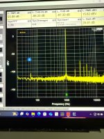
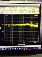
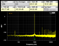
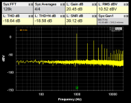
I recently purchased a Quant Asylum QA403 audio analyzer because I own a fair bit of old home and car audio equipment and I want to learn how to troubleshoot and repair them myself. All of the reputable repair shops in my area shut down long ago. I am a EE but I have not worked with analog circuits in decades. I am still learnoing how to use the QA403 but I thought I would post some screen shots from tests I have run on these amps, These are mostly THD plots at 1 kHz. It is readily apparent which channels are working and which are not. You can see a small peak at 60 Hz from the AC line feeding my power supply. First plot is a good channel. Second plot is a bad channel. All the bad channels look like this on both amps.
I recently purchased a Quant Asylum QA403 audio analyzer because I own a fair bit of old home and car audio equipment and I want to learn how to troubleshoot and repair them myself. All of the reputable repair shops in my area shut down long ago. I am a EE but I have not worked with analog circuits in decades. I am still learnoing how to use the QA403 but I thought I would post some screen shots from tests I have run on these amps, These are mostly THD plots at 1 kHz. It is readily apparent which channels are working and which are not. You can see a small peak at 60 Hz from the AC line feeding my power supply. First plot is a good channel. Second plot is a bad channel. All the bad channels look like this on both amps.
Attachments
I know about the ribbon cable issue with these amps and assumed replacement cables would be available. Perry already explained how to reseat my ribbon cable in another thread here. I thought I solved the problem by reseating the cable. Didn’t work.
PAC Parts only has one in stock today. I figure the first step is to replace the cables before going further. Luckily, I found a thread on DIY Mobile Audio about PDX F9 amps that gave me clues about finding a generic replacement. I ordered some 14 pin 0.5 pitch flat flexible cables from Mouser that are much less expensive than the Alpine part. I ordered 3 different variants to experiment with. I also ordered a service manual from PAC Parts.
I am hoping the replacement cables sort this out. If not, I will get more in depth with them. I figure this will be a good learning experience.
@Perry Babin I am interested in your repair tutorial. I corresponded with you some time ago about this but have not had the time to find an older laptop with an older version of Windows. I finally found a Dell with Windows XP. Will this work?
You don't need an old machine but it's generally better to have an old beater of a computer with a freestanding monitor (mounted on an articulated wall mount) instead of the expensive laptop that most people have nowadays.
XP should work.
It's odd that the noise is higher across the board.
Do the faulty channels have ANYthing in common? Inverted channels, Left/right? Front/rear? Same channels in both amps?
Is the point of shutdown related to input frequency? Speaker load? Will the channels shut down with no load?
Are the channels more likely to shut down with high vibration or when you push on various parts of the board, while playing?
On one amp, the faulty channels with high noise floor are both the left channels. I need to test the other one again but on that amp, only the right rear channel was bad if I remember correctly. I have run frequency sweeps and problem does not seem to be affected by frequency. In each case, i used a 4 ohm 200 watt load resistor from Parts Express. The channels will shut down with no load.. Don’t know about vibration yet. Have not tried pushing on various parts of the board while playing. This is complicated somewhat because I am still learning how to use the QA403. It is very different from using traditional volt meter and oscilloscope.
Does the way you connect the input to the analyzer make a difference? The channels are bridgeable and that means that one terminal (either positive or negative) has signal but on its bridging channel, those are reversed. Are you using the same input wire for the signal terminal in each test?
If I understand correctly, The PDX + speaker output on channel 1 is 180 degrees out of phase with + speaker output on channel 2. I am not sure that makes a difference in testing because I am only testing one channel at a time and running everything single ended for now.
I am moving the speaker output connector of the PDX from one channel to the next and moving the RCA input accordingly.
I am connecting the + output of the left channel of the QA403 to the amplifier RCA channel under test. I am only testing one channel at a time while I figure out the best way to connect things.
I have kludged together an input to the QA403 using BNC to Banana Jack adapter at the + input of only the left channel of the QA403. I have a 50 ohm cap on the negative inputs and the right + input. Then I have 12 gauge speaker wire from the banana plugs to the output of the amplifier.
Having said all that, I have not tried taking advantage of the differential input of the QA403. I am sure I could rig up a way to do that and it will improve the noise figures but I don’t see how that would affect what I have measured so far in terms of the huge difference between good and bad channels.
Am I missing something here? Would not surprise me if I am.
When making critical measurements, I feel it's better to be as consistent as possible. It will be easy enough to reverse the wires in the plug to put signal on the other input of the analyzer to see if it makes a difference.
Are you using an RCA shorting plug into the channels being tested?
Have you tried changing the various crossover and gain settings to see if they made a difference?
Are you tired of me asking you questions?
Are you using an RCA shorting plug into the channels being tested?
Have you tried changing the various crossover and gain settings to see if they made a difference?
Are you tired of me asking you questions?
Last edited:

I went back and retested the amp from Japan. Channels 1-3 look good. Channel 4 has the high noise floor like the trace I already posted. I used the same connector for each test run.
The other PDX has the same problem on 2 of its channels so whatever it is, this appears to be a common fault. That is what led me to guess the ribbon cables are bad.
The seller in Japan is one I have bought stuff from in the past and he has been accurate in his descriptions of the equipment he sells. The lower cost amp was purchased from a Pawn shop seller on Long Island who said it was in good condition and for $160 I was willing to take the risk.
The other thing I did not mention is that on the good channels, my portable OWON scope is able to sync to the sine wave of the test tone and it is a fairly clean looking waveform. On the bad channels, there is so much noise, the scope is not able to sync on anything even though there is a 1 kHz test tone you can see in the plot from the QA403.
I am saying this because to me, that means a signal is coming through that circuit from input to output but it has a ton of noise.
I am saying this because to me, that means a signal is coming through that circuit from input to output but it has a ton of noise.
I have tried various gain settings. Did not change how the bad channels behaved. I am not using RCA shorting plug on channels being tested. Not sure I understand the question. The channels being tested are getting signal from QA403. Do you mean I should use RCA shorting plugs on channels not being tested? I did not know you could do that with differential input circuits. I have not touched the crossover settings. I have all channels set for full range to bypass the crossovers.When making critical measurements, I feel it's better to be as consistent as possible. It will be easy enough to reverse the wires in the plug to put signal on the other input of the analyzer to see if it makes a difference.
Are you using an RCA shorting plug into the channels being tested?
Have you tried changing the various crossover and gain settings to see if they made a difference?
Are you tired of me asking you questions?
I am probably not going to do much with them today as I am still working full time as a contractor for NASA. With the goings on in Washington and DOGE, I’m worried about job security so M-F, my day job is the focus.
For critical measurements, you have to reduce the number of variables. The shorting jumper can do that, for some tests.
Did you check for noise levels with no input?
I'd suspect the output filter but that shouldn't cause a noise issue across the entire band.
Did you check for noise levels with no input?
I'd suspect the output filter but that shouldn't cause a noise issue across the entire band.
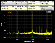
Tried something during my lunch break today. I opened the $160 amp, removed the ribbon cable from both boards and put Caig D100L on the contact surfaces. I reassembled and then cleaned all the speaker connectors with Caig. Retested the amp. Now the channels with high noise floor are the right channels. i am pretty sure the first time i tested it was the left channels that were bad. Another change is that the high frequency noise floor on the bad channels is fairly flat when it had a curve before. Not sure how the ribbon cable can cause this or if there is more than one thing going on but I am encouraged that this changed something. I have new ribbon cables coming from Mouser in a day or two. I will attach screen shots if I can find them. 🧐. I have a Mac with Parallels running Windows 11 and the Quant Asylum software is Windows only. The files are not visible to me right now because I am back in the Mac world.
I have noticed in videos by barevids about newer Alpine amps, that they got rid of ribbon cables.
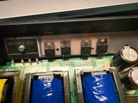
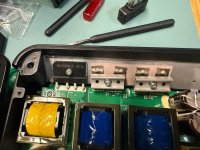
Well this next discovery really drives home buyer beware. I was so focused on the ribbon cable as suspect I completely missed this detail until I opened up the $160 amp from the pawn shop again. Someone worked on it and forgot to put it all back together. I am guessing these are the power supply FETS because the thing next to them looks like a bridge rectifier. Time to study the service manual. Second picture is of the PDX F4 from Japan.
Attachments
Last edited:
No the seller shipped it to me like that. I tried looking up the U channel pieces that clamp the FETS to heatsink on PAC Parts and looks like this part is no longer available. I am going to have to fabricate my own.
I have a buddy whose favorite saying is “Some things are so cheap you never stop paying for them”. I think this amp is going to be like that so i hope I learn a lot from figuring out how to get it working again.
I have a buddy whose favorite saying is “Some things are so cheap you never stop paying for them”. I think this amp is going to be like that so i hope I learn a lot from figuring out how to get it working again.
Ribbon cables came today from Mouser. Turns out the problem with the amp from the Japanese seller was the ribbon cable and I think I damaged it when I first opened the amp to look at the circuit board. I didn’t need to open it - I was just curious.
The replacement I bought is Molex Part # 98266-0150. The description on Mouser Electronics is - FFC / FPC Jumper Cables 0.5MM 152MM JUMPER 14CKT TYPE-D HI-TEMP. I believe the same cable is used in the PDX F6 and PDX V9.
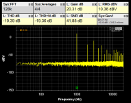
The other amp is still broken. New cable made no difference. @Perry Babin - I was careful this time to make sure my settings were identical for each test run. I tried varying gain and filter circuits and that had no impact on the bad channels other than filtering. Channels 2 and 4 have a high noise floor and the 1 kHz sine wave is difficult for my scope to synch to. Looking at the schematic for the preamp board, Channels 2 and 4 go through the same opamps from input to the ribbon cable connector. Channels 1 and 3 go through a separate set of opamps. 2 and 4 are the right channels. 1 and 3 are the left channels.
I am thinking next step is to trace a test signal through channels 2 and 4 on the preamp board to see what I can find.
@Perry Babin I downloaded the files on your web site to load on the Dell laptop with Windows XP. I will make sure the browser and Flash work and then order your tutorial.
The replacement I bought is Molex Part # 98266-0150. The description on Mouser Electronics is - FFC / FPC Jumper Cables 0.5MM 152MM JUMPER 14CKT TYPE-D HI-TEMP. I believe the same cable is used in the PDX F6 and PDX V9.
The other amp is still broken. New cable made no difference. @Perry Babin - I was careful this time to make sure my settings were identical for each test run. I tried varying gain and filter circuits and that had no impact on the bad channels other than filtering. Channels 2 and 4 have a high noise floor and the 1 kHz sine wave is difficult for my scope to synch to. Looking at the schematic for the preamp board, Channels 2 and 4 go through the same opamps from input to the ribbon cable connector. Channels 1 and 3 go through a separate set of opamps. 2 and 4 are the right channels. 1 and 3 are the left channels.
I am thinking next step is to trace a test signal through channels 2 and 4 on the preamp board to see what I can find.
@Perry Babin I downloaded the files on your web site to load on the Dell laptop with Windows XP. I will make sure the browser and Flash work and then order your tutorial.
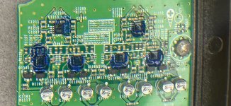
I am starting to study the Analog input board on the PDX to start troubleshooting. Attached is a picture of the op amps covered by blue coating that makes it impossible to see the chip name and covers all of the pins. Is this something to protect the pins from environmental conditions? When I worked for the Navy on aircraft engine computers, the circuit boards were typically coated with a ‘conformal coating’ that looked something like this. This looks like it makes it impossible to replace these chips if they are part of the problem. There are chips on the main circuit board that also have this coating on the pins but not all of the chips are coated. Does anyone know what this blue ‘stuff’ is?
Attachments
- Home
- General Interest
- Car Audio
- ALPINE PDX F4 troubleshooting - bought 2 Ebay amps and both have bad channels