Im looking at building this Class AB1 cathode biased amplifier based on this design here.
I have most of the components on hand, including a suitable power transformer and pair of OT's.
I am making a few changes, I am using an EF37A/6J7G instead of an EF86 and using 807 tubes instead of 6L6.
Few questions, is the 750pF capacitor across the CT to anode on the tube to remove oscillations? I find its odd only one half has this, ive never seen this before on such a schematic.
There is also an 820pf cap going across for the NFB loop, how critical are the values for these capacitors?
I have quite a bunch of silver mica caps on hand but nothing quite exact, ive got a few 680pF and 1000pF on hand if they will suffice.
Here is the schematic and a rough layout ive drawn of the turret board.
Another issue im unsure will be a problem is i mirrored the layout, so have to cross some wires over, not too sure if this is a worry, you will see what I mean with the channel on the left of the image.
The phase inverter was not too big of a deal, as i just swapped over each triode section.
Im unsure about the path of the heater wiring, but its just rough, I will probably move the tube sockets around some more and I have not included the power supply yet, but all the transformers will sit behind the 807 tubes at the bottom of the image. The filter choke im hoping will fit under the chassis.
This is appears to be a mish-mash of a couple of different Eico circuits. The 750pF cap compensated for differences in winding capacitances in the output transformer of the HF-60. If you don't know what output transformer this was intended for and swap in different tubes, all bets are off regarding stability and possible oscillation
Also, an 807 will not tolerate that much voltage on the screens. Well, it might, but you're taking a big risk. 400VDC is the max they will tolerate in normal use.
Also, an 807 will not tolerate that much voltage on the screens. Well, it might, but you're taking a big risk. 400VDC is the max they will tolerate in normal use.

I have a pair of transformers with a 7K primary which is close enough to the 6.6K target I was aiming for.
Regarding screen voltage on the 807, ive been running a guitar amp i built with 807 tubes at 400V and so far no issues, although there is a bit of debate on how far they can be pushed from what ive heard from radio HAMs who have run these things well out of spec, but since this amplifier is running in ultra linear mode, those screens dont directly see that voltage anyway and its quite safe to do so, from memory the screen will only experience a few tens of volts as its only seeing the voltage swing between the anode and the screen, i could be wrong, but thats how I understood it.
Another thing I forgot to add, is my OTs dont have a 16 ohm secondary, so not sure how this affects the NFB loop, can I just connect to the 8 ohm instead?
Last edited:
Right, with the cathode voltage subtracted from the B+ the 807s will be okay. But you can't just apply the same feedback network to any output transformer. Without knowing something about the original transformer the designer used, there's no way to know what the feedback resistor value should be, what level of feedback was intended, or what the phase-lead capacitor values should be. You can't just move what's shown to the 8 ohm tap. Do you have an oscilloscope?
Ah, found it. It's an Eico HF-22:
https://www.thetubestore.com/lib/thetubestore/schematics/Eico/Eico-HF-22-HF-35-Schematic.pdf
That amp used a 6.6K Chicago output transformer. I have a pair of them in the shed. So for the same level of feedback (presumably around 20dB), you would use about 2600 ohms from the 8 ohm tap. But again, the 500pF and 820pF caps won't be correct for a different output transformer. I'd suggest a single phase lead cap across the 2600 ohm feedback resistor. What that might be will depend on having a scope and experimenting with different values to reduce whatever ringing might be present with your output transformers.
What output transformers do you have? Not all transformers will handle 20dB of feedback.
Also, the circled cap/resistor network is a low-pass filter to reduce the bandwidth of the amp and avoid high-frequency instability. Again, these may not be appropriate values for your output transformers.

Right, with the cathode voltage subtracted from the B+ the 807s will be okay. But you can't just apply the same feedback network to any output transformer. Without knowing something about the original transformer the designer used, there's no way to know what the feedback resistor value should be, what level of feedback was intended, or what the phase-lead capacitor values should be. You can't just move what's shown to the 8 ohm tap. Do you have an oscilloscope?
Yes ive got an oscilloscope, so should come in useful for testing.
The transformer is a vintage Beacon S81, there is some data here https://dalmura.com.au/static/Beacon Radio 1958 Catalogue.pdfAh, found it. It's an Eico HF-22:
https://www.thetubestore.com/lib/thetubestore/schematics/Eico/Eico-HF-22-HF-35-Schematic.pdf
That amp used a 6.6K Chicago output transformer. I have a pair of them in the shed. So for the same level of feedback (presumably around 20dB), you would use about 2600 ohms from the 8 ohm tap. But again, the 500pF and 820pF caps won't be correct for a different output transformer. I'd suggest a single phase lead cap across the 2600 ohm feedback resistor. What that might be will depend on having a scope and experimenting with different values to reduce whatever ringing might be present with your output transformers.
What output transformers do you have? Not all transformers will handle 20dB of feedback.
look at page 14 for the data, it appears to have a 3D.B response @ 20 c/s
I see that the datasheet quotes it as suitable for this amplifier here (denco/osram 912)
https://oldamps.weebly.com/uploads/2/3/7/1/23714389/876183_orig.png
I think, the 750pF is too big value of capacitance for compensation (or the OPT is poor quality). The effective winding capacitance is a lot of smaller than the measured pri-sec value, because the voltage swing is not equal at all of winding surface. The 750pF (plus the trafo's own capacitance) can "eat" the high frequency power bandwith.The 750pF cap compensated for differences in winding capacitances in the output transformer of the HF-60.
Isn't too easy, unfortunately. Impedance-frequency curves can give help (half primary impedance at shunted another half primary and vice versa). You can tune with parallel capacity, until will be the point of resonance same. (Of course, the test must be repeat at shunted secondary too, and refine.) In practice is better the lossy (near-Zobel) compensation.
This is a method I would use to determine NFB-resistor and capacitor:Another thing I forgot to add, is my OTs dont have a 16 ohm secondary, so not sure how this affects the NFB loop, can I just connect to the 8 ohm instead?...Is there any easy way i can test the capacitance on this transformer?
At first, amplifier connected to 8 ohms dummy load, with GNFB resistor un-connected, feed such 1 kHz sine signal to input, that generates some 10 W (below clipping level) and monitor output with voltmeter and oscilloscope.
Connect GNFB with 10 k trimmer/potentiometer, which is set to max. resistance.
Adjust 10 k trimmer to the point where output level is decreased 12...14 dB.
This is safe and reasonable amount of GNFB. 20 dB is risky with not so perfect OPT.
Now you have reached correct GNFB level and trimmer can be substituted with correct fixed resistor.
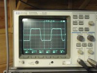
Then feed 10 kHz square wave signal to input to generate some 5...10 W output power.
Monitor the form of square wave with a scope. There may be some ringing etc. like in the attached picture.
Then start to add some capacitance in parallel with the GNFB-resistor to get as good square wave form as possible. Like at the second photo.
That is all you should need to get properly working amplifier.
Concerning 450 V as +Ub. I have built many fixed bias UL-PP tube amplifiers with 807's having 450 V as +Ub.
During last 10 years none of these have been needed output tube replacement.
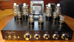
Attached the schematic of my amplifier.
Attachments

Yes ive got an oscilloscope, so should come in useful for testing.
The transformer is a vintage Beacon S81, there is some data here https://dalmura.com.au/static/Beacon Radio 1958 Catalogue.pdf
look at page 14 for the data, it appears to have a 3D.B response @ 20 c/s
I see that the datasheet quotes it as suitable for this amplifier here (denco/osram 912)
https://oldamps.weebly.com/uploads/2/3/7/1/23714389/876183_orig.png
Ah, well, that's a good OPT and was built for a feedback amplifier. But since it was intended for an EL84 amp and rated for 12 watts, you may be pushing it with 807s. The Eico HF-22 was 22 watts output. The tranny does appear to have the option for 3.7 to 15 ohms output.
Thanks, I will take a look at this.This is a method I would use to determine NFB-resistor and capacitor:
At first, amplifier connected to 8 ohms dummy load, with GNFB resistor un-connected, feed such 1 kHz sine signal to input, that generates some 10 W (below clipping level) and monitor output with voltmeter and oscilloscope.
Connect GNFB with 10 k trimmer/potentiometer, which is set to max. resistance.
Adjust 10 k trimmer to the point where output level is decreased 12...14 dB.
This is safe and reasonable amount of GNFB. 20 dB is risky with not so perfect OPT.
Now you have reached correct GNFB level and trimmer can be substituted with correct fixed resistor.
Then feed 10 kHz square wave signal to input to generate some 5...10 W output power.
Monitor the form of square wave with a scope. There may be some ringing etc. like in the attached picture.
Then start to add some capacitance in parallel with the GNFB-resistor to get as good square wave form as possible. Like at the second photo.
That is all you should need to get properly working amplifier.
Concerning 450 V as +Ub. I have built many fixed bias UL-PP tube amplifiers with 807's having 450 V as +Ub.
During last 10 years none of these have been needed output tube replacement.
Attached the schematic of my amplifier.
Can it damage the transformer if i have too much GNFB, or does it just affect the sound?
One question, how do I go about measuring the gain in dB? I take it i need an attenuator to make some calculations from what ive been reading.
Yeah I was a bit reluctant at first, but my mate reckons that these beacon transformers were fairly under-rated in their day, I would like to preform some tests, but what I can say is that its pretty large for a 12 watt transformer.Ah, well, that's a good OPT and was built for a feedback amplifier. But since it was intended for an EL84 amp and rated for 12 watts, you may be pushing it with 807s. The Eico HF-22 was 22 watts output. The tranny does appear to have the option for 3.7 to 15 ohms output.
Yes your right, these do indeed go to 16 ohms, from memory they have 2 secondaries that you either put in series or parallel to get the desired impedance.
Its called DIY layout creator, and I wish I knew about this some time back! Its quite useful and also can let you draw out schematics.Curious.....what program are you using to do that circuit mock-up?
Would be even more awesome if it could route your layout from the schematic itself, but that might be a few years off unless more contribute to the project in the future. But its pretty powerful for what I use it for, you can spend hours playing around for the most optimal layout.
Too much GNFB do not cause damage, but can cause the amplifier to oscillate.Can it damage the transformer if i have too much GNFB, or does it just affect the sound?
One question, how do I go about measuring the gain in dB?
Measure the voltage drop as I described. -12 dB is 0.25, -14 dB is 0.2.
So in my example above, if the output level to dummy load with no GNFB is 10 V, the proper output level with GNFB correctly adjusted would be 2...2.5 V.
If you measure the drop in voltage between no-feedback and feedback, there's a handy online calculator that will convert that to dB. ;-) I usually shoot for 5 volts RMS output with no feedback, then note the difference between no-feedback and feedback and enter that into the calculator. Between my Picoscope and the various online calculators, I don't have to do any math, thanks heavens.
Thanks, I will take a look at this once I get the thing built.
Main concern is that the transformer will be suitable.
I'm also looking at the filter network you mentioned in post #6, will this be a matter of experimentation also along with the capacitor across the OT primary?
Main concern is that the transformer will be suitable.
I'm also looking at the filter network you mentioned in post #6, will this be a matter of experimentation also along with the capacitor across the OT primary?
- Home
- Amplifiers
- Tubes / Valves
- Thoughts on this schematic/design?