I wouldn't necessarily assume that's all there is to it, or even that its the main factor. Class 2 and Class3 ceramics are nonlinear and piezoelectric. Class 1 ceramics (C0G/NPO) are low loss, sometimes too low loss. Then there is that clock oscillators are analog RF circuits, not digital.Do you also have an overall capacity of around 220nF?
If you would like to discuss in more detail bypass caps and or some thoughts on layout of bypass caps, layout of clocks, etc., please feel free to PM. Not that there is anything to hide, but I have already explained a lot regarding some of my views in various threads. No need to bore people who have already heard it enough times.
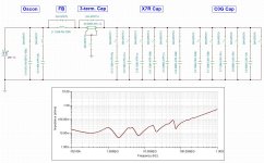
PDN (power distribution network) design and bypassing is a very intresting thing. A lot of capacitor manufacturers provide a proper spice model of the products and you can simulate your network transfer impedance (see e.g. picture attached).
@ Markw4: My question is, how good must be my PDN for a 50Mhz clock oscillator? What are the design steps? (some times ago I've created the excel sheet attached)
@ Markw4: My question is, how good must be my PDN for a 50Mhz clock oscillator? What are the design steps? (some times ago I've created the excel sheet attached)
Attachments
Well, first of all that's not exactly what we have here. What we have in one can/module is an oscillator (which is a sensitive linear circuit), a squarer (which is a quite nonlinear circuit), and maybe some associated support circuitry.My question is, how good must be my PDN for a 50Mhz clock oscillator?
There are some things we don't know about the significantly-black-box we call a clock module. We don't know its tolerance to voltage variations, if its more sensitive to voltage variations at certain times in the clock cycle and if so by how much, and how sensitive it may be to interference from magnetic fields associated with ground currents flowing underneath the oscillator. There may be other things we don't know too.
For Crystek CCHD-957 in particular, it is module that has some discrete parts in it (including one or more capacitors), and one plastic case IC. If it has a bypass cap inside the module, we don't know its value and or its parasitic inductance as viewed from the outside terminals where we might place a bypass cap.
Regarding PDN design concepts, I have mostly seen them applied to high speed digital, which is not exactly what a clock module is. Its more of an analog RF device, some of the performance characteristics of which are hard to measure, despite tending to have audible effects at some level depending in part on the particular internal architecture of a given dac being used with the clock.
Normally if we don't have a model of a device in question, we could try to figure out its tolerance for voltage variations by injecting noise into the PDS and observing at what point device failure occurs. However a clock module is unlike a high speed digital device. A clock doesn't simply fail at some PDS noise level, rather its performance degrades to varying extents as some function of PDS noise. Since degradation of its performance is hard to measure (phase noise measurement equipment is expensive to obtain, time consuming to perform statistical measurements, and does not exactly give all the information we would like to know), we have different problems to deal with as opposed to if it was an FPGA or something like that.
As a practical matter, historically speaking a number of different approaches to clock bypassing have been tried. That includes a set of C0G and or mixed C0G and C-II ceramic caps to try achieve a low inductance controlled damping bypass model. Most of that stuff sounded like crap in practice. And don't even get me started on the touchy subject of ferrites.
At some point a fellow forum member, @diyiggy, experimented with a newer type of SMD capacitor, acrylic (or similar) film caps. diyiggy found that the .22uf Rubycon MU cap sounded best in his opinion with Crystek CCHD-957. There was also a CDE .1uf film cap part in 805 size that was his second choice, but it now EOL.
For whatever reason I decided to try the caps diyiggy recommended, and damn if they didn't work they as he said. Since then a fair amount of experimentation and clock board building has occurred which tends to confirm that the small physical size Rubycon SMD film caps work well for dac clock circuits. That said, the same caps don't sound very good in analog audio frequency circuits, so IME they are of limited usefulness.
Thus some of us use the caps for practical reasons without having a more satisfying theoretical justification. I am okay with that since there are plenty of other dac design problems to work on. No need to speed excessive time trying to study why these particular caps seem to work as well as we think they do.
Last edited:

Hi, Thanks for the nice words Mark. It was 1 uF CDA acrylic in 2014 on the masterclock of IanCanada at the feet of the 14DIL socket. Nigth and Days, indeed. Then some years after when he poped up his Rpi hat line, he directly put under the pcb a 12 uF MU cap iirc, not sure about the capacitance value.
I further experienced with 0.1 and 0.2 uF in Dacs an op amps layout for voicing purpose and also at the back of Crysteck adaptator Iancanada made.
Result is huge you swapp from a Hifi sound to a beginning of high-end one (despite in the CCH-957 there are few X7R & COG caps under the metal shield.
I further experienced with 0.1 and 0.2 uF in Dacs an op amps layout for voicing purpose and also at the back of Crysteck adaptator Iancanada made.
Result is huge you swapp from a Hifi sound to a beginning of high-end one (despite in the CCH-957 there are few X7R & COG caps under the metal shield.
Most of the above is just opinions and have not been validated in controlled listening tests or measurements. And as is typical with opinions there are many who disagree with those opinions.
Unfortunately, I can't find any simulation model to this capacitor... The real problem what I see, that a correct A-B listening comparison with different type of caps at the oscillator is almost impossible.16MU224MZ22012
Another quite possibly more important thing than bypass cap is that with ASRC the clock frequency does not have to be a multiple of sample rate. Actually it may be beneficial to choose a frequency that is not related to either 44k1 or 48k family. IIRC ESS chose a 50MHz clock for their ES9039Q2M evaluation board. Another common frequency is 27MHz. So my suggestion is to choose either 27MHz or 50MHz clock as the alternative clock to Crystek.
True about ASRCs, no question. For that reason I tried to find a low-close-in phase noise 27MHz clock. No luck, but maybe someone else knows of one?
Without access to a 27MHz clock I liked, I went for fully synchronous USB dacs to start with. I suppose if enough dacs were going to be made, then some good 27MHz crystals could be ordered for use when ASRC is necessary.
Without access to a 27MHz clock I liked, I went for fully synchronous USB dacs to start with. I suppose if enough dacs were going to be made, then some good 27MHz crystals could be ordered for use when ASRC is necessary.
Last edited:
IIUC, it has to do with how frequencies are represented in the discrete domain, and harmonics of clock frequencies folding down into the audio band. @MarcelvdG could probably explain about it best. However IIRC some of it is in his tutorial article on building a tube dac. Please see attached.What is the technical background for that?
Attachments
As OP's alternative to Crystek 957 (CE3391) does not even specify phase noise it should be fairly easy to pick a clock with reasonably low phase noise.I tried to find a low-close-in phase noise 27MHz clock
For 50MHz e.g. this: https://www.mouser.fi/ProductDetail/ECS/ECS-2520MVLC-500-CN-TR?qs=QNEnbhJQKvamiSjavvIJCg==
And for 27MHz e.g. this: https://www.mouser.fi/ProductDetail/KYOCERA-AVX/KC7050K27.0000C1GE00?qs=rfsXwfL%2BOM8KH1fu78vjfg==
IMHO not good enough for Marcel's RTZ dac, but might work well enough for ESS. Someone would have to try it. Even for ESS I would still go for fully synchronous with better clocks for USB until proven ASRC can sound as good as fully synchronous. Might try 27MHz for SPDIF though...
Yes, even the frequencies are incorrect but at least the phase noise is hidden by the DAC's noise.IMHO not good enough for Marcel's RTZ dac
Not at all IME. Same for the guys using Iancanada SC Pure clocks. The effects of low close in phase noise are quite audible.
Of course, at higher offset frequencies then I would agree but then it would talking about noise floor which is not the same thing.
Of course, at higher offset frequencies then I would agree but then it would talking about noise floor which is not the same thing.
What is the technical background for that? (but honestly I do not plan to use ASRC...)
IIUC, it has to do with how frequencies are represented in the discrete domain, and harmonics of clock frequencies folding down into the audio band. @MarcelvdG could probably explain about it best. However IIRC some of it is in his tutorial article on building a tube dac. Please see attached.
I wrote something about the undesired frequency conversion effects you can get in a DAC and how frequency planning can help to minimize that in section 5 of the document Mark referred to, but what I wrote is incomplete.
Another issue, one that I wasn't aware of when I wrote the article, is the systematic jitter caused by the sampling in the sample-rate-ratio estimator in the asynchronous sample rate converter. Mind you, I never attempted to calculate whether this second effect is big enough to worry about.
The input word clock gets sampled by flip-flops running on the asynchronous ASRC clock. That means that the word clock edges get rounded to a nearby ASRC clock edge. This results in a systematic jitter pattern that repeats with the beat frequency of the input sample rate and the ASRC clock. As long as this beat frequency is high compared to the cut-off frequency of the jitter-suppressing filter in the sample-rate-ratio estimator, the systematic jitter is suppressed, but it isn't if the frequency difference is too small. You shouldn't get low beat frequencies when using an ASRC clock that has nothing to do with the usual audio sample rates.
At some point a fellow forum member, @diyiggy, experimented with a newer type of SMD capacitor, acrylic (or similar) film caps. diyiggy found that the .22uf Rubycon MU cap sounded best in his opinion with Crystek CCHD-957.
diyiggy, did you try 0.22uF NPO ceramic?
Alex.
I updated the labels for thin film/C0G and added the Rubycon bypass + series resistor of 50R.
I understand the approach for USB, unfortunately my streamer has no USB/IIS output, only S/PDIF. I am not sure for the suggestion of 27MHz, do you think it could work better in my scenario than 49,152MHz?
IMHO not good enough for Marcel's RTZ dac, but might work well enough for ESS. Someone would have to try it. Even for ESS I would still go for fully synchronous with better clocks for USB until proven ASRC can sound as good as fully synchronous. Might try 27MHz for SPDIF though...
I understand the approach for USB, unfortunately my streamer has no USB/IIS output, only S/PDIF. I am not sure for the suggestion of 27MHz, do you think it could work better in my scenario than 49,152MHz?
Attachments
How much current do you need at 5V? That LM317 might get pretty hot. I have one in a project that’s converting 32V down to 12V, and at 25ma the board is about 45C-50CHi, I updated the schematic:
- Added clock CCHD-957
- Added possbility two switch between this clock and CE3391 (I am curious I am able to hear a difference with my equipment)
- added an extra LDO for the clocks
- Added LM317 for +5V (from +24V DC)
- Added Meanwell DPBW03F-15 for +-15V (from 24V DC)
- fixed output stage acc. EVB v2.1
- added HW/SW mode switch
- added mute switch
- added possibility to access the I2C lines
- added TPA6120 as headphone amp (the discrete class a design will be added later)
- Home
- Source & Line
- Digital Line Level
- ES9039Q2M S/PDIF DAC design