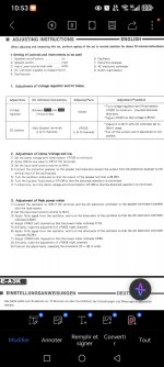
Good morning, I have just finished reassembling my Technics se-a3 and I am wondering about the adjustment of the quiescent current in the doc it indicates to adjust the potentiometer vr104 and vr105 to minimum but it does not indicate the direction and what is the minimum resistance level or the opposite? Sincerely
Attachments
I would say you turn VR104 to maximum resistance which will translate to minimum bias current but if unsure just monitor the bias current and turn to give minimum current.
VR105, no idea what this is. Some kind of soft clip limiter setting a limit on how much the amp can driven past its rated voltage output. If it has never been disturbed then I would leave it be.
Do you have a distortion analyser? because you most likely won't see distortion on a scope in a high feedback amp even with zero bias current.

I use an old HP8903 with bandwidth switched off measuring at 10 or 20khz. Injecting a small voltage sine wave from the analyser . There is less feedback correction at the top end of the frequency range so it's easier to see what the different bias settings do to the thd numbers.
I also check mains power draw and heatsink temp . Bias normally gradually increases, decreases and then settles over a period of time. I try and balance for low heatsink temp and respectable thd numbers.
I use this method if I don't know the spec bias of an amplifier.
I also check mains power draw and heatsink temp . Bias normally gradually increases, decreases and then settles over a period of time. I try and balance for low heatsink temp and respectable thd numbers.
I use this method if I don't know the spec bias of an amplifier.
Fair enough 🙂 and as you say you can see how the bias changes the numbers.
To make sure you turn it the correct way, just measure the voltage between the emitters of an output pair. According to the schematic, there should be 60mV between them. Make sure that all pairs have similar numbers. Dial it in to 60mV as an initial approximation and look at the distortion. Adjust as needed.
For the direction of the potentiometers I finally found it is the maximum resistance to have the bias at zero. I then adjusted to 20mv for the moment between tp1 and tp2, or did you see 60mv? Sincerely
Well, the emitter voltages are listed as 30mV and -30mV respectively, so if you measure from emitter to emitter, you should have 60mV. If you measure across a single resistor you should obviously get 30mV, but I prefer to measure between the emitters in case the resistors aren’t perfectly matched.
30mv across 0.47 ohm would correspond to the theoretical optimum value but its a lot of heat generation with four parallel pairs of outputs running on -/+75 volts (40 watts per channel heat dissipation at idle, 80 watts for two channel)
Considering that in my SE-A3 one of the channels was dead and all transistors were replaced with 2SC5200/2SA1943:
1/ Should I stick to the 60mA recommendation from the schematic?
2/ Right now after the amp is powered on the bias is ~10mA but after 20-30 minutes or so it goes up to 55-60mA (no signal applied).
Should I wait certain amount of time for the bias to settle (transistors warm up) BEFORE trying to adjust it?
3/ Considering I have a PC scope and a spectrum analyzer software is it enough just to watch the % of THD or I must use the method of observing it as recommended by the service manual?
Last edited:
1/ On balance that is probably best.
2/ You want the bias at the correct point when it is all warm. Play the amp at normal volumes for 30 minutes and then set the bias to the correct value and leave it at that.
3/ You could see if the resolution of the analyser is sufficient to see any changes.
On a practical note... you almost certainly will not hear any difference between different bias settings even down to currents as low as a milliamp or two, Also commercial designs are sometimes limited by heatsink and ventilation constraints and the optimum bias value for a given circuit is higher than the recommended bias setting.
Thanks for your reply. I was thinking in the same direction.
One thing I noticed was after a while at idle the transistors from both channels that are closer to the transformers are underbiased comparing to the outer ones. For example the transistor row ch R on the TPside measures 30mv, while the outer row is like 45mV. L ch a mirror situation.
I tested briefly at 100W (8 Ohm 300W dummy load) and current draw of all transistors was very close.
If the transistors are perfectly matched and if they are all at the same temperature then the currents will be equal between them all. Any difference in either of those two parameters will cause an imbalance and its something you can not do anything about in practice. One end of the heatsink will be different to the other for all kinds of reasons such as mountings and ventilation and so on and that will affect temperatures end to end.
Decide on the current you want to set and then use the pairs that you have found give the highest reading to set that nominal current and leave it at that would be my advice.
Remember that if you used the method of using an analyser as per the manual you would not actually be looking at exact currents and would be non the wiser 😉
Don't stress over it. Also try it on minimum current and ask yourself honestly if you can hear any difference between that and a normal bias current. If not then aim low, the amp will run cool and reliability will increase.
Don't stress over it. Also try it on minimum current and ask yourself honestly if you can hear any difference between that and a normal bias current.
Honestly I don't intend to. I don't have "golden ears" either 🙂
I apologize if I’ve disrupted your forum topic.
Hello. Have you ever experienced any issues with the left amplifier channel?
Technics SE-A3 Japan version 100V !!
I also installed Toshiba transistors, type 2SC5359 NPN and 2SA1987 PNP, but I’m having a problem with the left channel.
Actually, I’m not even sure if it’s the left amplifier — the orientation is reversed for testing, so what appears to be the left side from the front becomes the right side when the amplifier is flipped over (viewed from the bottom, with the legs up).
Anyway, here’s how I’ll explain it:
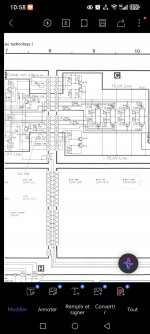
I slowly raised the voltage using a variac and measured the bias points TP1 and TP2.
I’ll describe it as seen when the amplifier is upside-down.
On the right-hand side (which would be the left channel from the front), everything worked fine. The relay clicked on, voltages were around 85.5V, maybe a bit higher, measured between TP4 and TP5.
The right channel works fine, and the bias was around 30mV.
Then I connected the AC voltage to the left channel.
Even during the slow power-up using the variac, I noticed some anomalies:
At just 30V AC input, the bias already jumped to 60mV.
At 50V AC input, the relays clicked on, and the bias jumped to 160mV — which is way too high.
The VU meter for that channel also jumped to the middle. Something clearly isn’t right.
I quickly powered it off to avoid burning the main output transistors.
What do you think I should do? Should I swap the driver boards from left to right to test?
I suspect this issue might have damaged the original DLPT transistors.
Before installing the Toshiba ones, I had installed new old stock DLPTs, which the technician burned out — the same issue occurred back then. He wasn’t able to find the cause.
That’s when I decided to go with the Toshibas, but now I’m facing the same problem.
I really don’t want to burn out another set of transistors.
Where should I start troubleshooting?
Thank you for any help you can provide.
Should I open a new thread for this?
Hello. Have you ever experienced any issues with the left amplifier channel?
Technics SE-A3 Japan version 100V !!
I also installed Toshiba transistors, type 2SC5359 NPN and 2SA1987 PNP, but I’m having a problem with the left channel.
Actually, I’m not even sure if it’s the left amplifier — the orientation is reversed for testing, so what appears to be the left side from the front becomes the right side when the amplifier is flipped over (viewed from the bottom, with the legs up).
Anyway, here’s how I’ll explain it:
I slowly raised the voltage using a variac and measured the bias points TP1 and TP2.
I’ll describe it as seen when the amplifier is upside-down.
On the right-hand side (which would be the left channel from the front), everything worked fine. The relay clicked on, voltages were around 85.5V, maybe a bit higher, measured between TP4 and TP5.
The right channel works fine, and the bias was around 30mV.
Then I connected the AC voltage to the left channel.
Even during the slow power-up using the variac, I noticed some anomalies:
At just 30V AC input, the bias already jumped to 60mV.
At 50V AC input, the relays clicked on, and the bias jumped to 160mV — which is way too high.
The VU meter for that channel also jumped to the middle. Something clearly isn’t right.
I quickly powered it off to avoid burning the main output transistors.
What do you think I should do? Should I swap the driver boards from left to right to test?
I suspect this issue might have damaged the original DLPT transistors.
Before installing the Toshiba ones, I had installed new old stock DLPTs, which the technician burned out — the same issue occurred back then. He wasn’t able to find the cause.
That’s when I decided to go with the Toshibas, but now I’m facing the same problem.
I really don’t want to burn out another set of transistors.
Where should I start troubleshooting?
Thank you for any help you can provide.
Should I open a new thread for this?
That sounds as if the amp could be bursting into instability/oscillation. You need to use a scope to see what is happening at the output and whether that is happening.The VU meter for that channel also jumped to the middle. Something clearly isn’t right.
So if I understood you correctly, I should input a 1kHz signal and use the oscilloscope to see what's happening? But as soon as the relay clicks, I'm afraid the output transistors might burn out.
Did you check ALL transistors AND diodes on ALL PCBs with a DMM in diode mode to make sure there aren't any short or open circuits?
Some of my thermistors were blown so I replaced ALL of them. Don't miss the germanium diodes on the driver boards. I would also check with DMM the resistors around the driver transistors 2SC5359 and 2SA1987. I had some blown in my amp that were replaced in a previous repair.
Some of my thermistors were blown so I replaced ALL of them. Don't miss the germanium diodes on the driver boards. I would also check with DMM the resistors around the driver transistors 2SC5359 and 2SA1987. I had some blown in my amp that were replaced in a previous repair.
ok i will check all these diodes and driver transistors. i changed 4 82kohm resistors on each board. because they showed the wrong measurement.
is there anything else critical that often breaks in this amplifier?
is there anything else critical that often breaks in this amplifier?
No need to input anything. Use the scope to look at the output before any speaker relay/s and see what it shows when the VU meter jumps up.So if I understood you correctly, I should input a 1kHz signal and use the oscilloscope to see what's happening? But as soon as the relay clicks, I'm afraid the output transistors might burn out.
- Home
- Amplifiers
- Solid State
- Technics SE-A3 bias adjustment