Yeah, I'm not sure if I like that too much. Makes it almost impossible to fix a broken tinsel lead, and the most lead flex going on near or right on the triple joint, which is where a break is most likely to happen. It does allow for more excursion however.
Depends on how it is sewn and conducted. If it is just in the top spider and not sewn too deeply, that looks fine, and also generous "wave" of the lead especially near the tripple joint makes it look very good with very little bending at excursion. But indeed in case of breaking, the sewn ones still will be a nightmare compared to normal ones.
is this a TL or a TH, asking cause on most of the TH designs you see expanding areas, hence the Horn name,
BP1 drawing do not have any expanding CSA
all bends are 90 degree angles.
i roughy modified with MS paint his sketch to add the expansion CSA
any sim differences between one and the other ?
better efficiency ?
or just easier to build as there are no angles
Last edited:

I was thinking that too, and there are some data on TL being basically same or less efficient in the eyes of Hoffman's iron law. I am all for getting most performance from the driver, but it must be steady performance not just peak sim, and it must make sense. I already do not like few things about the speaker being crammed into such space with such CSA, and any try that fails just gets insanely costly. But hey, I can easily postpone it and try in a month or two.
TL = constant expansion = sims in HR as a round pipe whereas a TH is expanding even if just a two step pipe and if the expanded pipe is at the closed end = inverse TH or often (mis) labled as a TQWT.
Re efficiency, when properly expanded we get greater efficiency over a wider BW, though in both cases actual box loading is limited to its Fhm:
Fhm = 2*Fs/Qts'
Fs: Fhm*Qts'/2
(Qts'): (Qts) + any added series resistance (Rs)
Fhm = 2*Fs/Qts'
Fs: Fhm*Qts'/2
(Qts'): (Qts) + any added series resistance (Rs)
We should just call them all 1/4 wave resonators and then add ‘expanding, constant or reducing path shape’ to distinguish’ ? The rest is forever confusing and makes us dumb people dumber (I get confused) 😝
I was thinking that too, and there are some data on TL being basically same or less efficient in the eyes of Hoffman's iron law. I am all for getting most performance from the driver, but it must be steady performance not just peak sim, and it must make sense. I already do not like few things about the speaker being crammed into such space with such CSA, and any try that fails just gets insanely costly. But hey, I can easily postpone it and try in a month or two.
Is the ‘1/4 wave resonator’ more or less efficient with the driver in the mouth or exposed as a ‘direct radiator’ ?
In many of @BP1Fanatic designs he covers the driver with a small crossectional area vent exit (the continued shape of his tapered pipes) and if I do that to any of my existing designs (where the vent is right next to the driver, but not covering it) it is quite obviously not as ‘loud’ , but maybe a bit of a filter?
Attachments
Last edited:
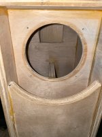
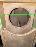
Stepped TH.View attachment 1418414
is this a TL or a TH, asking cause on most of the TH designs you see expanding areas, hence the Horn name,
BP1 drawing do not have any expanding CSA
all bends are 90 degree angles.
i roughy modified with MS paint his sketch to add the expansion CSA
View attachment 1418421 this is a "normal' TH
any sim differences between one and the other ?
better efficiency ?
or just easier to build as there are no angles
Technically, it's a positive flare TH since the CSA goes from 18.25" x 5" throat to 18.25" x 8" mouth.
Negative flare TH = Tapered-Tapped Quarter Wave Tube or Pipe (T-TQWT or T-TQWP).TL = constant expansion = sims in HR as a round pipe whereas a TH is expanding even if just a two step pipe and if the expanded pipe is at the closed end = inverse TH or often (mis) labeled as a TQWT.
Straight flare TH = Tapped Quarter Wave Tube or Pipe (TQWT or TQWP).
IcStepped TH.
Technically, it's a positive flare TH since the CSA goes from 18.25" x 5" throat to 18.25" x 8" mouth.
Pros and Cons of each ?Negative flare TH = Tapered-Tapped Quarter Wave Tube or Pipe (T-TQWT or T-TQWP).
Straight flare TH = Tapped Quarter Wave Tube or Pipe (TQWT or TQWP).
@Booger weldz
Depends on various details, but generally I´d say about same with bet on the magnet out being tad less efficient.Is the ‘1/4 wave resonator’ more or less efficient with the driver in the mouth or exposed as a ‘direct radiator’ ?
Negative flare is shorter and therefore doesn’t have all that harmonic resonace crap at the top of the bandwidth for a subwoofer. They really do sound fantastic.Pros and Cons of each ?
Like a gigantic vented box with no port noise
SAN184.50 excursion behavior around Xmax:
Very quiet. With real world signal though, some wind artifacts can be annoying even with this one.
Very quiet. With real world signal though, some wind artifacts can be annoying even with this one.
Hofmann's Iron Law...efficient, low, small...pick 2.
Positive flare TH = efficient & big.
Negative flare TH = low & small.
Straight flare TH = ease of build, no angles.
A stepped TH eliminates the angles, but Hofmann's Iron Law still applies.
Step up = efficient & big.
Step down = low & small.
Remember, a TH in it's simplest form (single fold) is only 7 boards just like a BR enclosure.
Negative flare is shorter and therefore doesn’t have all that harmonic resonace crap at the top of the bandwidth for a subwoofer. They really do sound fantastic.
Like a gigantic vented box with no port noise
FACTS!
Ask freddi about his negative flare stepped TH that I modeled and he had someone build for him.
I notice a stepped tapped pipe/horn has a big dead zone surrounding ~Fb x 4 (like all folded TL with driver @ vent) which might help with a crossover ? (Full wavelength, coming out the vent to the other side of the driver out of phase.)
Simple half and half split of the CSA in a single fold pipe (or similar)
If you do it with a horn flare that will create all kinds of crazy stuff up top and fill in the dead zone that otherwise was half silent conveniently
Simple half and half split of the CSA in a single fold pipe (or similar)
If you do it with a horn flare that will create all kinds of crazy stuff up top and fill in the dead zone that otherwise was half silent conveniently
Last edited:
It's about using the right driver specs (vented chart same for TL/horn):I was thinking that too, and there are some data on TL being basically same or less efficient in the eyes of Hoffman's iron law. I am all for getting most performance from the driver, but it must be steady performance not just peak sim, and it must make sense.
~0.403, Vb = Vas, Fb = Fs [MLTL]
< ~0.403, Vb = < Vas, Fb = > Fs [inverse tapered MLTQWT]
~0.403, Vb = > Vas, Fb = < Fs [expanding taper MLTQWT/MLhorn]
(Qts'): (Qts) + any added series resistance (Rs)
- Home
- Loudspeakers
- Subwoofers
- Review of LaVoce SAN184.50