Hello all,
I am working on my DIY Preamplifier new project based on the Elektor Preamplifier 2012 (Douglas Self) schematic.
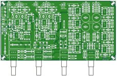
I don't need the TONE and BALANCE control sections in my design, painted in Red in the picture below. I will directly connect the output of IC2A pin 1 into the input of IC9B pin 5 (Green traces).
Still I have this question regarding the filters in the input of IC2A pin 2 and 3, painted in Yellow. Do I need them or they are part of the BALANCE section only?
And if needed, should I replicated the R11-R12-C6 filter with R8-R9-C5 connected to ground?
Thank in advance 🙂

I am working on my DIY Preamplifier new project based on the Elektor Preamplifier 2012 (Douglas Self) schematic.
I don't need the TONE and BALANCE control sections in my design, painted in Red in the picture below. I will directly connect the output of IC2A pin 1 into the input of IC9B pin 5 (Green traces).
Still I have this question regarding the filters in the input of IC2A pin 2 and 3, painted in Yellow. Do I need them or they are part of the BALANCE section only?
And if needed, should I replicated the R11-R12-C6 filter with R8-R9-C5 connected to ground?
Thank in advance 🙂
C5,6 set the high frequency response and offer additional RFI ingress protection as part of the balanced to single ended converter. C1,2 op at a higher frequency. Was this not explained in the circuit description text in the article? I’d have to look at my archives to see for myself.
If you don't need tone control and balance:
1. Do you need gain?
2. Do you need analog volume control?
If not connect K1 to K3 and you are ready. No caps, no noise or distortion of whatever kind introduced by the circuit, no power on/off plops, just nothing.
1. Do you need gain?
2. Do you need analog volume control?
If not connect K1 to K3 and you are ready. No caps, no noise or distortion of whatever kind introduced by the circuit, no power on/off plops, just nothing.
YesIf you don't need tone control and balance:
1. Do you need gain?
Yes2. Do you need analog volume control?
I still want to choose between 5 different sources, plus one TAPE MONITOR. I designed my inputs with relays switched by soft-touches based on the Adafruit Industries AT42QT1070 development module.
The outputs of the DIY Preamplifier will drive my DIY Amplifier (posted in a previous thread here).
I read back the Elektor article. It seems that the R8-R9 are part of the BALANCE section and that the R11-R12 resistors are include only to preserve the CMRR of IC2A. I didn't read any mention of C5-C6. So if I get ride of the resistors R8-R9-R11-R12, I wonder if I still need the C5-C6 capacitors, that are in parallel of the R8-R9, also in parallel for 500 Ohms total.
With this change, R19 provides positive feedback which promotes instability.
You want to delete R19.
In your modified schematic, R115, 215.
Jan
You want to delete R19.
In your modified schematic, R115, 215.
Jan
No..Are your 5 inputs and tape monitor balanced? And does your diy amplifier have balanced inputs?
No balanced inputs nor requirement for balanced output? Why use a balanced design when you have no requirement for one? balanced is used for low noise external inter-connections usually from a microphone. You have line level inputs from un-balanced sources. Power amps usually have a balanced to un-balanced ckts inside.
I could see if you had the pcb set and wanted to make use of them but for a new design, crazy amount of op-amps to make a technical point of having the lowest noise but for what? noise is kinda like distortion, there are points in which going lower does not really make it sound any better.
the final test has always been, hold your ear to the sensitive speaker and crank the gain. I can see if its a no cost adder but it is $ and power wise. Have fun. design is about making choices.

Hum.. Well it is my first experience with OPAMP. Of course I read a couple of books on the subject but my attempt was to start with a very good design that has a good reputation and make it to my needs.No balanced inputs nor requirement for balanced output?
I wasn't sure if the balanced inputs was or not necessary to keep the original design to it's specifications. I admit you made a good point.
So, am I right to think that this new schematic below, minus the Red painted section and with the Green wires added, is enough to a pre-amplifier left channel Input stage?Why use a balanced design when you have no requirement for one?
@jan.didden I removed R115,215.
Are you sure switching Audio GND at each input is a good idea?
BTW the input section around U22 is still balanced. Maybe you should first decide what you exactly need. IMHO you can do this with just 1 (one) dual opamp or 2 excellent single opamps like OPA828, normal volume control and with less coupling caps (in way lower values) too. Keeping stuff simple is both cheaper and more effective. The less there is the less that can go wrong. If you like your woofers you could add power on/off muting too as power on/off plops are the mosquitos of audio. If you don't do anything they will always sting.
BTW the input section around U22 is still balanced. Maybe you should first decide what you exactly need. IMHO you can do this with just 1 (one) dual opamp or 2 excellent single opamps like OPA828, normal volume control and with less coupling caps (in way lower values) too. Keeping stuff simple is both cheaper and more effective. The less there is the less that can go wrong. If you like your woofers you could add power on/off muting too as power on/off plops are the mosquitos of audio. If you don't do anything they will always sting.
Last edited:
Are you sure switching Audio GND at each input is a good idea?
I have a TV set that is far away that I still want to connect. This unit is the only one in my actual setup that does generate a tiny noise when it is connected. Seeing that even when not selected at the source input of my actual pre-amplifier, the noise is still present, it must come from the GND connection. If I unplug the 1/8" stereo adapter from the earphone socket at the TV set, the noise is totally gone. That means the noise is not coming from the cable, but from the TV set. When I watch the TV, the volume is loud enought to totally cover the noise, but when I listen music from another source and the volume is very low, I could hear the noise to the point where I simply disconnect the 1/8" stereo adapter from the TV set to fix it and make the noise totally goes away.
So it was first my goal to have at least one input with the GND switched off when not selected, to connect the TV set into this input for the trick above. That explain my design based on the Elektor Preamplifier 2012 with the original balanced inputs that all GND are switched off.
And if you thing of it, the final result would be like if all my input cables into the pre-amplifier are simply disconnected physycally, no? I don't see the problem there.
BTW the input section around U22 is still balanced. Maybe you should first decide what you exactly need.
If you refer to my last post, I simply modified the left channel in the schematic as an example to discuss the modification before I modify the entire drawing.
Ah OK. Anyway, it will likely give plops when switched on/off and it will plop when switching sources. You see no problem and that is OK but disconnecting cables physically is usually done when stuff is powered off which is really something different.
You could switch inputs from for instance TVs not analog but via digital input selection of a DAC. No ground loop/hum/spurious sounds/noise either.
You could switch inputs from for instance TVs not analog but via digital input selection of a DAC. No ground loop/hum/spurious sounds/noise either.
Last edited:
You have a good point there... I didn't though about it.but disconnecting cables physically is usually done when stuff is powered off which is really something different.
So the good way would then be to remove also all relays that disconnect the GND. That is a very less expensive solution seeing the price of these relays.
But I am still facing my problem for this TV set.
And what about the schematic modifications above in post #11 to remove the balance section. Is it alright or do I miss something?
Without knowing the device that well K6 and K7 seem unbalanced L and R outputs.
K5 is called “Tone defeat” which normally is a bypass for tone control. This is done with relays in this device. You could omit tone control and the relays if you don’t need that.
K5 is called “Tone defeat” which normally is a bypass for tone control. This is done with relays in this device. You could omit tone control and the relays if you don’t need that.
Last edited:
Hi, Jean Paul,
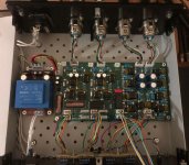
Thank you for your answer. I made this preamp and I'm using it. I don't know what k5, k6 and k7 are in the circuit, so I didn't make the connections. Because I don't know how to make a connection. There are two problems in the circuit, the first is that the balance adjustment does not work exactly. Secondly, there is a lot of noise when the sound is full low.
Thank you for your answer. I made this preamp and I'm using it. I don't know what k5, k6 and k7 are in the circuit, so I didn't make the connections. Because I don't know how to make a connection. There are two problems in the circuit, the first is that the balance adjustment does not work exactly. Secondly, there is a lot of noise when the sound is full low.
Attachments
It are line outputs without volume control.
I can not support a device by Elektor/D.Self and solve the apparent imperfections (IMHO the device is unnecessary) but I can say you forgot to connect the PE pin of the IEC inlet with green/yellow wire to the chassis. This should be corrected.
If you connect a pin of K5 to + Vre and the other one to GND the relays will be activated and the tone control will be bypassed.
Should all be described better in the article really.
Last edited:
- Home
- Source & Line
- Analog Line Level
- Elektor Preamplifier 2012 new personal project