thanks bp1 its been interesting. here we go with more dumb questions. how should test the frequency response. obviously im not putting this thing up in the air so ground plane method is what i think will be the best way. I will be doing it outsdie with ample room so how far away should i test from? and how far should i be putting the mic from the ground? I was planning on just using the little stand that the mic came with. the speaker will be laid on its side as i plan to stack them like that when in use. if someone could advise me on the best way for me to test them, I shall get started. Going to hook everything up now.
Most of the manufacturers specs are done 1W at 1meter.
If you have a calibrated SPL meter you can point it at the mouth for the sub and make sure your are at 100cm (1M) of the mouth.
If your driver is 8ohms you feed it a 60hz sine wave and with a voltmeter at AC not DC and measure 2.83v , that way you will now you are feeding 1W to the driver.
Your calibrated SPL will read the amount of Decibels your cabinet is making.
Then you compare with your sims.
Then with REW you can run the sweeps and capture the whole response graph of your cabinet.
There are several articles on how to measure with REW
Hope this helps
Last edited:
Construction looks good!I will be doing it outsdie with ample room so how far away should i test from? and how far should i be putting the mic from the ground?
Two meters from the mouth is a fairly standard distance for single subwoofer testing, though 10meters would be preferred if a huge test area is available.
The mic diaphragm should be as close to the ground plane as possible.
Wind noise is often a problem outdoors, I generally use a foam windscreen and lay the screened mic on a piece of plywood to keep it clean.
Voltage can be increased to give a 1meter/1watt equivalent, 2.83 (for 8ohm) to 5.66 accounts for the 6dB loss from two to one meter,
or 4volts for 8ohms. A 10 meter distance would require 10times the voltage, 100watts for a 1/m 1/w equivalent.
A longer distance reduces signal to noise ratio and increases influence of any boundaries, shorter distance may be approaching the near field, reducing accuracy.
Your measured impedance of 8ohms at 24.56 ohms and ~7.5ohms at 55Hz appears to be around double what was simulated.
Looks more like an 8ohm driver than 4ohm.
What is the driver's DC resistance?
Art
No, most are done at considerably longer distance and power and scaled to the standard of 1w/1m, or a specified voltage.Most of the manufacturers specs for the freq response are done 1W at 1meter.
All the Danley Sound Labs subwoofer measurements are done outdoors at 10meters and 28.3volts.

Now I know , I was based on the fact that the specs published says 1W at 1m but I was not aware that they scale the graphs.
So what they don't say what really happens behind "closed doors"
I'm learning more about the theory everyday 😎
So what they don't say what really happens behind "closed doors"
I'm learning more about the theory everyday 😎
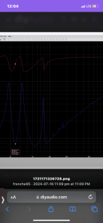
Hmm... that's actually pretty far off. So much so that it looks like an entirely different build than what was sim'd.View attachment 1334619
the purple is hornresp and the green is my dats. to be honest im not sure how close of an exact match is considered acceptable or what the difference between mine and the sims means when relating the 2.
Firstly, the peaks in the impedance curve should never be higher than the Hornresp prediction. If they are, that usually means that the build doesn't match the sim and/or the driver's real t/s parameters don't match what was used in the sim. If the build matches the sim, the peaks will be at very near the frequencies in the sim's impedance curve, and the height of the measured peaks will be less, and typically noticeably less, than the heights of the peaks in the sim.
Secondly, the upper resonance frequencies in the build's impedance curve are noticeably lower than those in the sim. This suggests that the build is tuned noticeably lower than the sim that's supposed to represent it. This could be caused by a number of reasons, e.g. the actual path length is longer than the calculated path length, or the mouth of the build is restricted too much by the driver's motor.
Finally, the first impedance peak is noticeably HIGHER in frequency than the corresponding impedance peak in the sim. This could be caused by a few factors, but in my experience one of the common ones is that there is a leak around where the driver is bolted to the cabinet, which could be caused by the hole in the cabinet being slightly too large (the mounting diameter quoted for drivers is for use when the driver is mounted through the hole, not on top of it - for the latter mounting type, the diameter should be reduced by a few mm).
I've attached below a similar impedance curve comparison for one of my builds, where the build (blue) is a pretty close match to the sim (red).
Ya I saw your comment this morning got out of bed to go check things and the reason it looks like a different sim is because it is SMH I was comparing to the wrong sim on my computer like an idiot....I didn't have time to post the layover of the sim that matches the build before I had to go to work. It's does look alot closer it's still not perfect but better. I will try to maybe spread some silicone around the edge of the woofer but I didn't cut the hole to big. I use the stencils from mobile Audio solutions for cuttibg my baffles I never use what they say on the driver specs. I take a circle router template, put in either around or on top of the sub depending on how it's being mounted and use that. With that being said maybe the foam that the kraken comes with for you to put as a gasket had a week spot or something. I'll try and use small touch of silicone if it changes something or seems to work I'll pull the woofer and change the gasket. I also wondered if it could be caused by me raptor lining the inside of the box and stuff before I mounted the sub down idk who knows I'll figure that out when I'm off work today.
@welter. As for the 8 ohm ready I have no idea how it's getting that or why because it's a single 4 ohm voice coil. In the dats I took this morning to compare to the correct sim it was 6.5 ohms where it said 8 in the previous one. That is a bit of mystery to me. At the peak in 50s it says like 38 ohms or some ****. Has anyone ever had it do that to them?
I'll post everything later but ya my enclosure is 40 deep 38 high not 36 with .29 not .3 another question could the wheels rattling on it cause any of the outcomes you spoke about Brian?
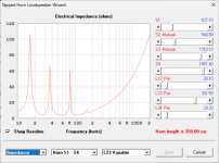
Here is what i got after building another one. this time i made sure i could read a piece of paper SMH! nothoing like a 350 dollar piece of fire wood. we will just act like that never happened lol I did use some polyfill in this one and i havent fully finish putting the final touchs on it yet. raptor liner for paint, mouth bracing, etc. let me know how far off I was on this one. I also have not double walled the sides as i am not sure if it is needed yet. idk im sticking with this one i suppose pending today frequency response test. so it is what it is on this one
mine is red horn resp green
Attachments
Last edited:
am i supposed to add any smoothing to this? idk i gotta do some research on this but this is what the enclosure got.
Did you smash those two big resonances above 100hz with a filter or did they not actually exist (fingers crossed 😝) ?View attachment 1340194
am i supposed to add any smoothing to this? idk i gotta do some research on this but this is what the enclosure got.
Attachments
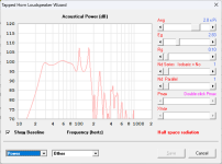
It's got crossover set at 95hz but48. I played around with the crossover some I never ran a test with no low pass on it. I went up to 125hz on it but would overall get the same exact test results just a little less slope depending on how high I went with the low pass. It also had a high pass set at 20hz but48. Other than that I didn't do anything to it. That is at 1 meter. Im going to get some other test in from further away soon but I'm just trying to get these 4 enclosures done so I can get them out of my way. Lol 😂.....I also don't know exact wattage the test was at. Pretty low tho. I just had it up enough to make the levels be corect in rew. This is the first time I've actually ran test and stuff on any of the builds I've done so new to this whole part.

I also used Pollyfill batting on certain parts inside so that could have possibly eliminated the simulated spikes somehow idk. Just a guess I honestly don't know
is there anyway i can simulate the drivers coming out of the side on MLT3 like if i were to take them from where they are in the boxplan and just rotate them?
Just a heads up to BOXPLAN users - it looks like the way Hornresp saves Driver data was changed, which basically breaks the "import driver" routine built into most of the workbooks.
Older versions of Hornresp saved driver data as follows:
B&C 15TBX100-4
Sd=855
Bl=22.25
Cms=0.000125
Rms=6.24
(etc.)
However the latest versions of Hornresp save it like the following:
B&C 15TBX100-4
Sd = 855
Bl = 22.25
Cms = 0.000125
Rms = 6.24
(etc.)
Basically "=" was replaced with " = " in the specific text file holding the driver's data. This change basically breaks the "Import Driver" routine in the BOXPLAN workbooks.
Interestingly enough it doesn't seem to bother Hornresp if either "=" or " = " is used in the driver text file (otherwise it wouldn't be able to read driver data exported from the BOXPLAN workbooks).
With over 35 BOXPLAN workbooks that use the same Import Driver routine, it will be a challenge to update all of them. If when running the Import Driver routine in a BOXPLAN workbook the macro generates an error, simply open up the driver's text file and remove the extra spaces (Replace " = " with "=" and save it). The Import Driver routine should work after that.
- Home
- Loudspeakers
- Subwoofers
- Spreadsheet for Folded Horn Layouts...