Hi there,
After building the PL519, design of KeesB, I asked him if he had a nice sounding Push-Pull design.
Which he had and he asked me to draw up the schematic of the EL84 Push-Pull direct coupled and asked me to share this in a new thread.
This amplifier is build up with a ECC83 direct coupled to an EL84 Push-Pull end-stage. This is an interesting version which I also build and which sounds sweet.
For questions you can reach out to KeesB.
Attachments

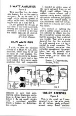
I built this amp some 30 yrs ago and have tried several variants with current sources for the 84's capacitor coupled etc. but found that it sounded less natural than with a common Rk. The idea came from some of the most used driver schematics from the sixties in which a triode connected EF86 was direct coupled with ECC 82 followed by PP EL34's (The mu of EL 84's triode connected (19) was almost the same as that of an ECC 82 (17)).
The result was a very good sounding simple amp and although the pwr output is no more than 5w it appeared loud even with 87db speakers. I hope some of you will try it too because its certainly worth the trouble.
The result was a very good sounding simple amp and although the pwr output is no more than 5w it appeared loud even with 87db speakers. I hope some of you will try it too because its certainly worth the trouble.
This amp design shows three big disadvantages: Both output tubes need to run in class A, the common cathode resistor isn't big enough for proper balancing (a CCS would cure it), and there's a lot of power loss in the common cathode resistor. It's the most wasteful design one can imagine.
Best regards!
Best regards!
Current draw is ca. 50ma. I tried a ccs but the sound deteriorated, it became less natural. The aim was to build a simple very good sounding amp requiering a minimum number of parts, The powerloss because of the common Rk is 4,5 W.
Replace the 1.8K with a choke.
Choke DCR + a series resistor needs to be 1.8k, for the same DC bias on the output tubes.
Or, RC couple, and the choke DCR and series resistor can be lots lower than 1.8K, because the output grids will be at 0V.
I have done self inverting amplifiers like that, with RC coupling, 0V bias grid, a 5H 200mA Hammond choke, + series bias resistor (5H 200mA does not saturate at low frequencies that are lower than 2 X power mains frequencies). The tradeoff is low inductance, versus saturation at low frequencies.
I used 6V6, and 6CK4 tubes in the outputs. Both versions worked well, my systems "sounded" good.
The reason the output tube cathode resistor is 1,800 Ohms . . . 25mA/output tube . . .
50mA x 1,800 Ohms = 90V. The cathodes are at 90V, because the output tube grids are at about 80V, so there is 10V bias grid to cathode.
No coupling cap.
With a coupling cap, the cathodes with 50mA total . . . 5H 200 ma choke (DCR 65 Ohms), in series with 135 Ohms, gives 200 Ohms. 5H and 135 Ohms in series from the output tube cathodes to ground.
200 Ohms x 0.050 A = 10V Bias.
The coupling cap drives the top output tube grid, ground the bottom tube grid through a 1k grid stopper to ground. the top grid is now 1k + 6800k to ground. 470k or 330k might be safer than 680k to ground.
These are all self inverting amplifiers, the driver tube is single ended, the output tubes are the phase inverting stage. Self inverting push pull.
At 50 Hz, 5 henry choke is 1570 Ohms of inductive reactance, almost as good as 1,800 Ohms.
At higher frequencies, the 5 H is superior to the 1,800 Ohm resistor, the self inverting action is better.
And, with the coupling cap, and the 5H and 135 Ohm series resistor, there is less power waste.
Try it, you will like the "sound" of the amplifier.
Last edited:
neodymium,
To be accurate and correct, check the following . . .
The driver tube is DC coupled to the top output tube grid.
C3, is not a coupling cap. It puts the bottom output tube a AC ground (a very low frequency).
That allows the output stages to operate as a self inverting push pull stage.
Check out the more efficient, 5H solution I propose. (works good for my 6V6 and 6CK4 output tubes).
C3, 0.47uF and 680K have a pole frequency of 0.497 Hz.
The top grid is driven by DC from the driver plate.
The bottom grid does not get any signal from the driver plate, when the signal is 5 Hz or higher.
The only non DC coupled is the output transformer. They do not pass DC. Which means there is no DC offset at the speaker, which would displace the woofer coil and cone from mechanical center. Sounds like an advantage to me.
This circuit is often misunderstood. But it does work.
A cleverly designed output transformer can make this absurdly high cathode resistor obsolete. For example, see the schematics of the German radio Tonmeister by Koerting, built between 1957 and 1960. Sorry, due to copyleft issues an upload isn't allowed for me.
Best regards!
Best regards!
Yes, that's it exactly. Thank you!
Last year I've parted out an irreparable Tonmeister with rotten case (must have been standing in the rain for some time...), broken dial glass and a single replacement speaker of unknown provenance. The electrostatic tweeters were both missing also. So I have it's OT handy. Unfortunately it doesn't transform into suitable load impedances 🙄 ...
Best regards!
There is very interesting compound phase splitter (current and voltage). Another nice element is the 2nd grids feeding for better DC filtering, with UL-like feedback.
Thx for sharing!
Thx for sharing!
Do you think so? In my opinion the point is to compute the turns ratio so that the common cathode signal is out of phase, of course, and it's level is half the upper tube's grid signal level. It's a matter of voltage exclusively, with the help of the common cathode resistor to completely balance both tubes.
Best regards!
Best regards!
What kind of distortion does this Tonmeister splitter circuit develop? The derived splitter V is more like two distortion sources down the chain now.
The earlier cathode derived splitter V at least was cathode follower degenerated, now it's plate derived and load dependent. If it had good global Fdbk, then the plate source should be fairly accurate. But then, does saving an inverter element justify another isolated winding on the OT?
I guess they didn't have super $0.35 devices back then:
Last edited:
R4 was meant for global feedback and in some amps I actually used it (3k3 to the ot) but mostly left it out (I built a number of this type of amps). I wanted to keep the possiblity to use it although it's not really necessary as its distortion is quite low without it.
I really can't answer to your 1st question, smokingamp, as the data given by the radio manufacturers never mentioned THD figures.
Anyway, I'm completely with you that trying to save a dedicated phase inverter by a self balancing output stage always is a very poor crudge, see my contribution #3 also. The limitation to class A in a PP arrangement is the poorest crudge of all. I never ever would spend any effort with that, as we have well proven PI designs.
We must note that in the 1950ies to 1960ies Koerting radios were produced for the then big German mail order house Neckermann, hence needed to be produced as cheaply as possible in order to compete in the market. I noticed the tube sockets that were spot welded to the chassis instead of being riveted, which was standard for other reputable manufacturers of the time. Indeed, I assume that the additional secondary winding tap was cheaper to manufacture than the cost of an additional PI triode with it's socket and it's passive components.
Best regards!
Where ever did you get such an idea?? And where are your experimental results?Replace the 1.8K with a choke.
All my stuff on that amp, with & without the Hammond choke were published here
on DIY in 2017. Look them up.😀👍
The idea is ancient, a way to market & claim PP when it was a buzz word.
Here is one from WW2 when the experimenters junk boxes were running out.
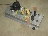
And my own real circuit in hardware.
Attachments
- Home
- Amplifiers
- Tubes / Valves
- EL84 Push-Pull direct coupled by KeesB