Hello, a bit ago the amp suddenly died when sitting at idle and not playing anything, after that when trying to power it up just pops the speakers and goes into protect.
I only have some basic knowledge of amp repair. The tools I have are a scope, multimeter, thermal probe and soldering iron.
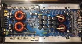
In the amp I was able to identify 1 dead output fet (B31N20D), but I also wanna check the overall health of the amp and if everything is working like it should, as it has been repaired before by someone else.
Currently I've removed all of the output FETs for testing, it seems to power up fine, but I found that a KSP92 transistor on a card gets very hot (over 70c). Along with some other transistors on the card being about 50c.
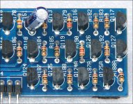
The card:

What would be the next steps? The KSP92 isn't shorted according to the multimeter.
Some observations:
One side of the output side:
Gate: 0v (has some sort of pulses)
Drain: +64v
Source: 0v (has some sort of pulses)
The other side:
Gate: -78v
Drain: 0v (has some sort of pulses)
Source: -74v
EDIT: measuring output section without and with signal (37hz sine wave) applied
One side gate:


One side source:


Other side gate:


Other side drain:


Speaker outputs:


Edit 2:
Removed the hot KSP92, but seems there are 2 of them in parallel, so now the other one gets hot.
Measured what's going to the removed transistor:
Base and emitter: about 84v
collector: pulses
why would they be getting so hot?
I only have some basic knowledge of amp repair. The tools I have are a scope, multimeter, thermal probe and soldering iron.
In the amp I was able to identify 1 dead output fet (B31N20D), but I also wanna check the overall health of the amp and if everything is working like it should, as it has been repaired before by someone else.
Currently I've removed all of the output FETs for testing, it seems to power up fine, but I found that a KSP92 transistor on a card gets very hot (over 70c). Along with some other transistors on the card being about 50c.
The card:
What would be the next steps? The KSP92 isn't shorted according to the multimeter.
Some observations:
One side of the output side:
Gate: 0v (has some sort of pulses)
Drain: +64v
Source: 0v (has some sort of pulses)
The other side:
Gate: -78v
Drain: 0v (has some sort of pulses)
Source: -74v
EDIT: measuring output section without and with signal (37hz sine wave) applied
One side gate:
One side source:
Other side gate:
Other side drain:
Speaker outputs:
Edit 2:
Removed the hot KSP92, but seems there are 2 of them in parallel, so now the other one gets hot.
Measured what's going to the removed transistor:
Base and emitter: about 84v
collector: pulses
why would they be getting so hot?
Attachments
Last edited:
What's the circuit board designation for the hot A92?
The transistors Q124/A and 125/A all run very hot and can fail. They may check OK with a meter but won't work at normal switching frequencies. I'd replace all of them, cleaning all solder/pads for them (and any near that have overheated solder) before I do much else.
I used to add fans to these amps. It's extra work but helped with reliability.
Attachments
Unsure what you mean by "What's the circuit board designation for the hot A92?"
But the hottest transistor was Q117, but after removing it Q116 heats up instead. There were a couple of warm transitions on the card, but nowhere near those 2.
Should replace all of the transistors on the card? hopefully won't be too expensive.
When ordering them I'll also order a set of output FETs, what would be a good substitute for the B31N20D? They are very expensive.
Someone suggested the IRFB4227.
The KSP92 is the same as an MPSA92.
Q117 runs hot, normally. On the older amps with fans, this and the Q124/5 transistors were installed so they were closer to the fan (not an option here).
Replacing all of the transistors is up to you. I don't know what you consider (too?) expensive. I would only replace the ones that are typically a problem. Some may not be available from a reputable distributor.
The 4227 may be too much of a load for the already marginal driver circuit. The IRFB38N20D has been used fairly often and may only require a slight adjustment in the CCS on the driver board.
The 38N20D will work, it is way cheaper than the 31N20D (1.5eur cheaper per unit). And the MPSA92 also are fine in price.
Which ones usually are the problematic ones? As at 16 cents per unit I can afford to replace more than necessary.
Q117, Q124 and Q125?
Which ones usually are the problematic ones? As at 16 cents per unit I can afford to replace more than necessary.
Q117, Q124 and Q125?
Those transistors do run hot and without additional cooling (especially in hot climates), they are a temporary fix without additional cooling.
Have yuo tried installing the surviving output FETs to see if it would power up and produce audio?
Have yuo tried installing the surviving output FETs to see if it would power up and produce audio?
I haven't tried installing them to see if it will produce audio. Sadly that won't be possible this work week because I took the amp and tools with me to my internship hours way from home, but left the fets at home.
Had a feeling I forgot something
Should I wait until Friday so I can install the existing FETs back in or order new FETs and transistors and replace them sometime mid this week?
Had a feeling I forgot something
Should I wait until Friday so I can install the existing FETs back in or order new FETs and transistors and replace them sometime mid this week?
It's up to you. Do you have any output FETs that might be suitable to test the amp?
If not, you can power it up (with the driver board repaired) to see if you get drive at the output FET gates.
If not, you can power it up (with the driver board repaired) to see if you get drive at the output FET gates.
No suitable output FETs on hand.
I would be ordering the transistors and the output FETs at the same time.
There was something on the gates, so it isn't completely dead right now.
I'll order the new transistors and FETs and come back here when the I replace the transistors.
Is there anything else I should order?
I would be ordering the transistors and the output FETs at the same time.
There was something on the gates, so it isn't completely dead right now.
I'll order the new transistors and FETs and come back here when the I replace the transistors.
Is there anything else I should order?
I don't know what you have on hand. If you need to adjust the CCS current, a 470-1k potentiometer will save some time.
Replaced the transistors on the card
One side gate:

Other side gate:

It is looking cleaner, but is this on the speaker terminals normal? (37hz sine wave on the RCAs, still without output side FETs). seems to have a bunch of DC offset, more signal resulting in more offset

Edit: also it still has a high pitch noise in the hearable range. seems to be coming somewhere on the PSU side.
One side gate:
Other side gate:
It is looking cleaner, but is this on the speaker terminals normal? (37hz sine wave on the RCAs, still without output side FETs). seems to have a bunch of DC offset, more signal resulting in more offset
Edit: also it still has a high pitch noise in the hearable range. seems to be coming somewhere on the PSU side.
Last edited:
What's the frequency on the gates of the PS FETs?
Where was the negative/ground for the waveforms?
Fully isolated scope (battery powered with no connection to the mains)?
Where was the negative/ground for the waveforms?
Fully isolated scope (battery powered with no connection to the mains)?
Ps fets about 22.8khz
For the output terminal reading it was on the output negative, battery negative terminal for the rest
The amp is being powered by a wall powered PSU, but the scope is battery powered
For the output terminal reading it was on the output negative, battery negative terminal for the rest
The amp is being powered by a wall powered PSU, but the scope is battery powered
When using a mains-powered scope in differential mode (note for others) or using an isolated scope (you), place the negative terminal on the source leg of the FET when viewing drive signals.
Don't let the ground clip short from the drain pad to the source pad. Solder a short jumper wire to the source pad and clip to that if shorting is possible.
With no outputs in the circuit, there is no feedback and no ability to drive the output of the amplifier in any way (to correct for offset).
Don't let the ground clip short from the drain pad to the source pad. Solder a short jumper wire to the source pad and clip to that if shorting is possible.
With no outputs in the circuit, there is no feedback and no ability to drive the output of the amplifier in any way (to correct for offset).
Got some time and I installed the output FETs, there is some fault in the amp still.
It tries powering on a few times, then goes into protect
output terminals get negative rail on it when it tries powering on
Edit:
One side gate gets negative rail on the gate when it tries to power on
other side gate always has negative rail on it
It tries powering on a few times, then goes into protect
output terminals get negative rail on it when it tries powering on
Edit:
One side gate gets negative rail on the gate when it tries to power on
other side gate always has negative rail on it
Last edited:
They are being annoying and won't come out, don't wanna heat them for too long and kill them either.
What if you apply new solder, enough to allow the soldering iron tip to heat all 3 terminals at once, then lay the iron across all 3 terminals. Will that help get them out?
Sadly the iron tip isn't long enough to heat all 3 at once, tried 2 but it's barely too short to heat up both at once
With some more solder I can heat up 2 at once and with more struggling I have gotten one out, 3 more to go
- Home
- General Interest
- Car Audio
- Ural Warhead 1.1800 repair and overall health check