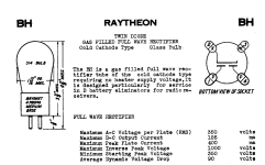
Hi everyone, hope all is well. This is the latest design that I came up with for a Low mu pre-amp with autoformer. Very simple design with a quiet power supply. The pre-amp is intended to drive a 10K impedance. Input will be a 2Vrms digital streamer. I can't find much user experience on the BH rectifier, other than the spec sheet (attached). Would like your thoughts on this design.
Attachments
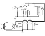
You have B+ tied directly to the autoformer which will likely burn it out and the triode doesn't get any voltage as you don't have a plate load connected to the B+. You need a resistor, a plate choke or some other type of plate load.
The mercury rectifiers were the real deal 🙂 Have a few that are 98 years old and still work. Deliver a whopping 1.3A.
Last edited:
It needs an input RC filter because of today's pollution. Since it has an open input this is not luxury.

I have enjoyed the 866A, but want a full wave rectifier. The 83 works, but it has never sounded good in my amps. The 83 always sounded un natural with a solid state harshness.The mercury rectifiers were the real deal 🙂 Have a few that are 98 years old and still work. Deliver a whopping 1.3A.
Please explain, JP. I am not following.It needs an input RC filter because of today's pollution. Since it has an open input this is not luxury.
Did not use these in audio, they were used in 1924 battery chargers here.
@sidn28790 https://www.electronics-tutorials.ws/filter/filter_2.html
@sidn28790 https://www.electronics-tutorials.ws/filter/filter_2.html
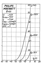
B405 has about 2k5 Ri.
IMO without low output impedance active load ("gyrator" or cascode CCS) the -parafeed- loading of AVC would be problematic.
The TVC/AVC requiring low source impedance for good behaviour.
IMO without low output impedance active load ("gyrator" or cascode CCS) the -parafeed- loading of AVC would be problematic.
The TVC/AVC requiring low source impedance for good behaviour.
Until now I didn't know cold cathode rectifiers existed other than MAR. What gas(es) do these use.
Looks like this rectifier needs 350Vp to start
Why have the 0.68uf cap, are you trying LC or CLC. The manufactures doc you provided shows 40mf as first cap.
And there is mention of a 90v drop for your tube. Interestingly the OZ4 linked has only 24v drop; MV territory.
Looking at the curves for B405, Ra looks to be closer to 3k and mu 5
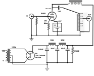
Look at the B405 heater, you have 13V in one pin, and -9V in the other. How do you get that negative voltage?OK, the new schematic has the plate choke inserted and the B+ is no longer tied to the autoformer. See below.
gupsta - good catch on the starting voltage and drop. I need to change the rectifier.
jcalvarez - the intent is to use filament bias. Thus, you are correct and I have revised the schematic to show the (-) battery terminal connected at the bottom of the filament resistor.
Anyone know of a rectifier that will start with 165V or 265V? My transformer secondaries are 165V or 265V. Possibly solid state.
Attachments

the starting voltage is Vpeak so 1.41 x your RMS (no load). I note OZ4 also has a minimum current draw, which may apply to some degree to other cold cathode gas rectifiers. Some people use hybrid, gas/vacuum/solid state in a bridge configuration. Lots of choices to pick from.
If your into gas tubes, perhaps a VR 150 or 105 tube might be of interest.
If your into gas tubes, perhaps a VR 150 or 105 tube might be of interest.
Not familiar with simulation software myself but this seems a case where it might be more effective than the ask-answer method.
It's filament biased DH tube.Look at the B405 heater, you have 13V in one pin, and -9V in the other. How do you get that negative voltage?
The "right" side of filament has +13V, the "left" side on the 60R filament bias resistor the potential is +9V (4V filament voltage, 0.15A).
The (grounded) grid has -9V relative to the "left" leg of filament, so bias voltage about -11V (9V+half of filament voltage).
Thank you. I understand filament bias. My point was about "-9" next to the left heater pin. Changing that to "+9" solves the problem.
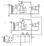
Hi everyone, hope all is well. I am posting the final (hopefully) schematic. Notice the tube rectifier has been replaced with solid state rectifier diodes. Also, I am using an L413 tube which is very similar to the B405. This is the first time I have built a "stereo" pre-amp using a shared power supply, so please let me know if this looks correct. Each tube will be pulling 15mA current, so the total draw on the Power Supply is 30mA.
Also, since the input goes thru a TVC, is a grid leak resistor still required?
Thanks for any input.
Also, since the input goes thru a TVC, is a grid leak resistor still required?
Thanks for any input.
Attachments

- Home
- Amplifiers
- Tubes / Valves
- New pre-amp: B405 with BH rectifier