I handed out PCBs for this BJT Simple Matcher jig, during talk#3 at Burning Amp yesterday. For those who couldn't attend, I've attached the Gerber .zip file below. You can send it to a PCB fab and have some boards shipped straight to you.
If you haven't yet ordered PCBs from an online fab, it's fairly easy and painless. Here's a brief explanation: Ordering PCBs online (using Gerber files): A walkthrough -- featuring the fab "JLCPCB"
Unfortunately, some of the figures in my "slide deck" didn't render very sharply on the projection system, so I've included the entire presentation below in .pdf format which features infinite resolution vector graphics. The presentation slides are fairly self-explanatory, so this Forum post includes only a few addenda:
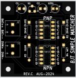
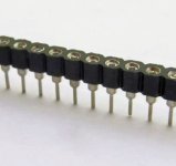
1. There are sockets for four transistors on the board. Two 5-pin sockets for PNP transistors, and two more 5-pin sockets for NPN transistors. These are arranged so that if you happen to own some 10-pin DIP sockets {which are uncommon}, you can fit two 10-pin DIP sockets on the board. Otherwise just fit 5-pin single inline "breakaway" sockets as shown in the picture attached below. I handed these out to BAF24 attendees; they are inexpensive if purchased from eBay. Here are a few eBay product titles:
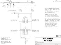
2. The circuit schematic diagram in .pdf format is attached below. That's the one to print, since .pdf has infinite resolution. Instructions for using the Simple Matcher jig appear right there on the schematic. And of course, also in the presentation slides.
3. To maximize the life of the 9V battery, I'm deliberately running the LED indicator at very low current. Please compensate for this low current by fitting a super bright LED. The LED part number called out in the Parts List attached below, shines at nineteen thousand milli-candelas. That's pretty bright.
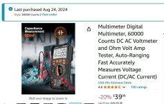
4. As promised during the talk, I've included an image of the inexpensive handheld meter I purchased for matching, which has 0.1% basic accuracy and whose DC voltage display goes down to tenths of a millivolt. It's not the only possibility, it's probably not the very best, but it's relatively cheap and relatively easy to buy. However, as emphasized during the discussion, you will get "a lot better than nothing" matching results, even with the cheapest meters that only go down to 1 millivolt resolution.
5. The schematic includes printed instructions which tell you how to use the BJT Simple Matcher PCB. Just print out the (.pdf) schematic and bring it to the measurement lab, on the day when you're doing the matching work.
6. "AIR LOCK BOX"?? During my BAF presentation, an audience member's question (@ timestamp 27:29 in the YouTube video) included a remark that in his own matching efforts with another jig, it was useful to cover the entire test jig with a (removable, 5-sided) box made of insulating foam or foam-core. This minimized air currents around the two transistors being measured, and therefore sped up the thermal equilibration of the transistors. If I'm remembering correctly, his arrangement took about 60-90 seconds to get a stable delta-VBE reading {on a different jig}, whereas my slide deck says 90-120 seconds for this BJT Simple Matcher jig with no box. So it might be a quick and inexpensive experiment that you may wish to try; possibly a box could speed up your hour-and-a-half marathon of matching. Several attendees were also concerned that the human test operator's breathing, might create unwanted air currents which slowed the equilibration process. An insulated box separating human and jig, might mitigate these concerns. I speculate that a box 125 x 125 x 75 mm (5 x 5 x 3 inches) would be a handy size to easily cover the BJT Simple Matcher board and wire leads.
_
If you haven't yet ordered PCBs from an online fab, it's fairly easy and painless. Here's a brief explanation: Ordering PCBs online (using Gerber files): A walkthrough -- featuring the fab "JLCPCB"
Unfortunately, some of the figures in my "slide deck" didn't render very sharply on the projection system, so I've included the entire presentation below in .pdf format which features infinite resolution vector graphics. The presentation slides are fairly self-explanatory, so this Forum post includes only a few addenda:
1. There are sockets for four transistors on the board. Two 5-pin sockets for PNP transistors, and two more 5-pin sockets for NPN transistors. These are arranged so that if you happen to own some 10-pin DIP sockets {which are uncommon}, you can fit two 10-pin DIP sockets on the board. Otherwise just fit 5-pin single inline "breakaway" sockets as shown in the picture attached below. I handed these out to BAF24 attendees; they are inexpensive if purchased from eBay. Here are a few eBay product titles:
Code:
    50Pcs 40Pin 2.54mm Single Row Round Female Pin Header Socket gold plated

    10 Strip Tin PCB Panel Female IC Breakable 40 pin 2.54mm Row Round Header Socket

    10Pcs 2.54mm Pitch 40 Pin Single Tin PCB Panel IC Breakable Round Female Header

    5x Strip Tin PCB Panel Female IC Breakable 40 pin 2.54mm Row Round Header Socket

2Pcs 40Pin 2.54mm Single Row Round Female Pin Header Socket gold plate3. To maximize the life of the 9V battery, I'm deliberately running the LED indicator at very low current. Please compensate for this low current by fitting a super bright LED. The LED part number called out in the Parts List attached below, shines at nineteen thousand milli-candelas. That's pretty bright.
4. As promised during the talk, I've included an image of the inexpensive handheld meter I purchased for matching, which has 0.1% basic accuracy and whose DC voltage display goes down to tenths of a millivolt. It's not the only possibility, it's probably not the very best, but it's relatively cheap and relatively easy to buy. However, as emphasized during the discussion, you will get "a lot better than nothing" matching results, even with the cheapest meters that only go down to 1 millivolt resolution.
5. The schematic includes printed instructions which tell you how to use the BJT Simple Matcher PCB. Just print out the (.pdf) schematic and bring it to the measurement lab, on the day when you're doing the matching work.
6. "AIR LOCK BOX"?? During my BAF presentation, an audience member's question (@ timestamp 27:29 in the YouTube video) included a remark that in his own matching efforts with another jig, it was useful to cover the entire test jig with a (removable, 5-sided) box made of insulating foam or foam-core. This minimized air currents around the two transistors being measured, and therefore sped up the thermal equilibration of the transistors. If I'm remembering correctly, his arrangement took about 60-90 seconds to get a stable delta-VBE reading {on a different jig}, whereas my slide deck says 90-120 seconds for this BJT Simple Matcher jig with no box. So it might be a quick and inexpensive experiment that you may wish to try; possibly a box could speed up your hour-and-a-half marathon of matching. Several attendees were also concerned that the human test operator's breathing, might create unwanted air currents which slowed the equilibration process. An insulated box separating human and jig, might mitigate these concerns. I speculate that a box 125 x 125 x 75 mm (5 x 5 x 3 inches) would be a handy size to easily cover the BJT Simple Matcher board and wire leads.
_
Attachments
-
 PCB_topview.png78.9 KB · Views: 1,341
 -
 raster_image_Matcher_schematic.png103.1 KB · Views: 1,304
 -
 Breakaway_SIP_socket.jpg95.5 KB · Views: 1,551
 -
 handheld_meter.jpg124.6 KB · Views: 1,013
 -
BAF24_Slides_BJT_Matcher.pdf2.6 MB · Views: 508
-
Excel_Parts_List_BJT_Simple_Matcher_revC.zip2.8 KB · Views: 260
-
Gerbers_BJT_Simple_Matcher_revC.zip46.5 KB · Views: 227
-
BJT_Simple_Matcher_schematic_rev_C.pdf35.6 KB · Views: 363
Last edited:

Many thanks for this Mark - that will be very useful, I will get one made up.
Can I also ask, on page 5 of your pdf slide presentation you mention "Yes it will drive an F4" a new bonus pcb that has its own diyAudio thread. I can't find it on the forum, do you have a link to it, thanks.
Can I also ask, on page 5 of your pdf slide presentation you mention "Yes it will drive an F4" a new bonus pcb that has its own diyAudio thread. I can't find it on the forum, do you have a link to it, thanks.
I've decided to wait until revision B of "Yes It Will Drive An F4" is complete, before uploading to the Forum. If you want to get a headstart by studying the mechanical layout and wiring requirements, I believe (but cannot guarantee) that revision B will be externally identical or very similar to revision A. It is possible but not mandatory, to mount revision B PCB directly above the F4 PCB as a Double Decker ("piggy back"), using the existing F4 mounting holes + 20mm spacers. When they get uploaded to the internet, watch the BAF-2024 videos for more.
What's the schedule? I don't know.
Tell me more about X, Y, and Z? You'll have to wait for revision B.
What will happen at the Store? I don't know.
Who will organize a Group Buy? Whoever volunteers.
And that's about all I have to say, until rev B is posted.
_
What's the schedule? I don't know.
Tell me more about X, Y, and Z? You'll have to wait for revision B.
What will happen at the Store? I don't know.
Who will organize a Group Buy? Whoever volunteers.
And that's about all I have to say, until rev B is posted.
_
Attachments

Last edited:
I'd like to present a couple examples of the switcheroo verification procedure mentioned in "how to do it (part 4)" on page 11 of the BJT Simple Matcher presentation, which is an attachment to post #1 of this thread. There was "no math, no equations" in the BAF-24 presentation. But here, a week later, you will find some math in this little appendix.
The theme of this post is: unfortunately, our equipment is not perfect. The 0.1% 2K49 ohm resistors on our jig are not perfectly matched to each other. The sockets don't have identical resistances. Our $49 digital voltmeter is not perfect. Everything is cheap and imperfect.
For analysis purposes, we will lump all of these error sources, into one single number called "Systematic Equipment Error".
The entire measurement apparatus (jig + test leads + DVM) displays an imperfect, incorrect delta_VBE which is XXX millivolts greater than the true-and-correct delta_VBE. I will call this XXX millivolts discrepancy, the Systematic_Equipment_Error.
displayed_delta_VBE = true-and-correct-delta_VBE + Systematic_Equipment_Error
Naturally we wish that our apparatus would have a Systematic_Equipment_Error equal to zero. Or we wish that it is a very small number, less than 0.1 millivolts.
Fortunately the switcheroo verification procedure, allows us to cancel out the Systematic_Equipment_Error and thereby get a good estimate of the true-and-correct-delta_VBE. Let's see how that works.
CASE 1
Suppose the Transistor_A's true-and-correct VBE is 700.000 millivolts
Suppose the Transistor_B's true-and-correct VBE is 702.000 millivolts
(then the "right answer" which we hope our equipment will display, is Delta_VBE = Mismatch = -2.000 mV)
HOWEVER, suppose the Systematic_Equipment_Error is +0.37 millivolts. We don't own a perfect digital voltmeter, our two 0.1% resistors on the jig
are not perfect ideal clones, etc. All of the imperfections in our cheap little rig, add up to an SEE of +0.37 millivolts.
displayed_delta_VBE = true-and-correct-delta_VBE + (+0.37mV)
For the first half of the verification switcheroo procedure, we plug A into the left socket and we plug B into the right socket. After patiently waiting 120 seconds, our cheap little rig says:
displayed_delta_VBE = (700.000 - 702.000) + (+0.370) = -1.630 millivolts
The right answer is -2.000 but thanks to SEE, the jig says -1.630
For the second half of the verification, we perform the switcheroo. We leave everything else the same but interchange (swap) the transistors.
We plug A into the right socket and we plug B into the left socket. After patiently waiting another 120 seconds, our cheap little rig says:
displayed_delta_VBE = (702.000 - 700.000) + (+0.370) = +2.370 millivolts
And now we do the calculation:
Actual_delta_VBE = (displayed_VBE_first - displayed_VBE_second) / 2
Actual_delta_VBE = ( (-1.630) - (+2.370)) / 2
Actual_delta_VBE = (-4.000) / 2
Actual_delta_VBE = -2.000 millivolts
Hallelujah! Our cheap little rig, which includes nonzero Systematic Equipment Error, has given the right answer thanks to the switcheroo. It's delightful!
CASE 2
Transistor_A's true-and-correct VBE is 690.3 millivolts
Transistor_B's true-and-correct VBE is 690.1 millivolts
(then the "right answer" which we hope our equipment will display, is Delta_VBE = Mismatch = +0.200 mV)
This time, Systematic_Equipment_Error is -4.44 millivolts.
For the first half of the verification switcheroo procedure, we plug A into the left socket and we plug B into the right socket. After patiently waiting 120 seconds, our cheap little rig says:
displayed_delta_VBE = (690.300 - 690.100) + (-4.440) = -4.240 millivolts
Then we perform the switcheroo; A into the right socket, B into the left:
displayed_delta_VBE = (690.100 - 690.300) + (-4.440) = -4.640 millivolts
And now we do the calculation:
Actual_delta_VBE = (displayed_VBE_first - displayed_VBE_second) / 2
Actual_delta_VBE = ( (-4.240) - (-4.640)) / 2
Actual_delta_VBE = (+0.400) / 2
Actual_delta_VBE = +0.200 millivolts
Another Hallelujah! Our cheap little rig, got the right answer again, even in the presence of Systematic_Equipment_Error. The math worked.
Last edited:
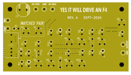
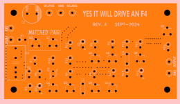
I just posted rev.B of the example circuit "Yes It Can Drive An F4" which greatly benefits from tightly matched BJTs.
Last month at the Burning Amp Festival, I presented a little PCB called BJT Simple Matcher. That BAF talk, plus some photos, the matcher schematic, and the PCB Gerber file, are available on the diyAudio Forum (here). At the very end of the talk, I showed a little example circuit which greatly benefits from BJT matching, named "Yes It Can Drive an F4" (revision A).
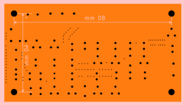
A couple of small tweaks later the newest release (rev B), which I hope is the final release, is presented here in this thread. You can see a top view of its unpopulated PCB, and also the circuit schematic...
A couple of small tweaks later the newest release (rev B), which I hope is the final release, is presented here in this thread. You can see a top view of its unpopulated PCB, and also the circuit schematic...
Well I have all the parts on hand for the BJT Simple Matcher by @Mark Johnson , except I thought I had 4.7k for R4, but closest I have on hand is 4.75k. From the schematic, it appears that R4 is just dimming the LED, so 4.75k should be totally fine from that perspective..... however, I wanted to ask just to be sure I'm not missing something.
I realize it's probably a dumb question, but I have been known to ask many of them, so apologies for another.
I realize it's probably a dumb question, but I have been known to ask many of them, so apologies for another.
From the schematic, it appears that R4 is just dimming the LED, so 4.75k should be totally fine from that perspective
You are correct in your schematic reading.
🙂
Where's my "That was easy" button at.....
View attachment 1380925
Went together fast. Now I just need to wait for my 100qty BJT's to match.
As a way to pay forward @Mark Johnson 's generosity, I have 3 extra "completion kits" for folks who already have the PCB board + female headers handed out by Mark at BAF (or I suppose grabbed some from a board house). I will ship to you inside the continental US for free and you can pay forward to someone else down the road. @uptownsquash has one reserved if he'd like as I know he was at BAF for the talks. Do I have two more greedy boyz interested in the kit who already have the PCBs on hand?


[EDIT] Reserved:
@uptownsquash
@wg45
View attachment 1380925
Went together fast. Now I just need to wait for my 100qty BJT's to match.
As a way to pay forward @Mark Johnson 's generosity, I have 3 extra "completion kits" for folks who already have the PCB board + female headers handed out by Mark at BAF (or I suppose grabbed some from a board house). I will ship to you inside the continental US for free and you can pay forward to someone else down the road. @uptownsquash has one reserved if he'd like as I know he was at BAF for the talks. Do I have two more greedy boyz interested in the kit who already have the PCBs on hand?
[EDIT] Reserved:
@uptownsquash
@wg45
Last edited by a moderator:

Will this measure JFETs?
Thanks DualTriode
It might be a good idea to rephrase the question-- to make it more general and more open ended (?) Perhaps something like
Does anyone see a way to make this BJT Simple Matcher PCB, match other types of semiconductor devices besides Bipolar Junction Transistors? Does anyone see a way to make this PCB match JFETs?
- Home
- Amplifiers
- Solid State
- BJT Simple Matcher -- test jig presented at 2024 Burning Amp Festival