Sure Hans, my pleasure. I was out for rest of life, bun now quickly run it:Drbullj,
Could you apply a ca. 0.3mV 1khz tone to your amp and process this the same 3x way as the spectra in #417.
Hans
Bottom trace is direct input from attenuation (same diagram as post #399) It reads something like 330uV
Other 3 traces are FFT 16k, 256k and 512k, peak 1kHz on all of those 3 is about 655 mV.
Otherwise, here is better explanation of FTT (fast Fourier transform) lengths: https://www.roomeqwizard.com/help/help_en-GB/html/primer.html
🙂 , I do agree Hierfi, That version of 1812 is not my favorite, even except cannons it does have some nice passages. I like other 2 records to listen .The cannon shots on the Telarc overloaded the digital recording as I recall. This doesn't follow that the LP would be cut at high levels, though it seems Telarc would record it this way in order to capture and highlight the wide dynamic range of the digital process, a process they were selling.
Maximizing the undistorted signal to noise ratio seems the primary issue. A cannon shot... or alternatively allowing for the near field recording of a nuclear weapon going off... wouldn't leave much room to record normal signals above the noise floor... if the recorder hasn't taken up smoking in its near field response. Increasing the undistorted signal headroom reduces the signal to noise ratio of lower level signals that may be sonically impacted as a result. Fidelity is about resolving harmonic structures, vocal inflections and other characteristics reliant upon resolving low level signals either in absence of noise, or being able to hear through it. Allowing for anomalies such as cannon shots can deteriorate the sonic virtues of all else being listened to. Some overloads ought to be ignored... particularly on records never played for any sonic enjoyment.
Nevertheless, crazy as it is , it is still probably highest dynamic material recorded on commercial LP, worth for testing purposes, needle tracking ability for sure...
Me to, but being a skeptic to well established truths as I am, I want to check it myself. Trigger is that I never heard anything strange while playing with 2x60db first stage gain, and still see nothing close to clipping...I find it a bit hard to believe that Karlov and Happ, working for Sure at the time were so wrong in their analysis.
O.k, processing seems at least to be partly correct, but I can’t see wether REW is averaging or really keeping the maxima, because I still don’t understand why in #417 the orange peaks aren’t equal or above the blue ones.Sure Hans, my pleasure. I was out for rest of life, bun now quickly run it:
Would it be possible to put those 3 recordings in a .wav file and send them to me ?
And yes, now I get your 16, 256 and 512 FFT, which was meant to be 16K, 256K and 512K.
Hans

Hi Hans,
These are maximum values for sure, I did not save averages.
It could be that in post #417 I simply mixed up naming while I was in speed to do it, that would explain....
I will send you waw-s but not tonight, tomorrow if I manage
Sorry I had to edit my own post, getting too confused to type on phone...
Last edited:
The other thing about overloading a circuit is the time it needs to recover.
When it’s in the nanoseconds, you probably wouldn’t notice anything at all, but when in the milliseconds, you will be able to hear it.
This can easily be tested when combining a sine wave with large pulses that are overloading the amp.
Hans
When it’s in the nanoseconds, you probably wouldn’t notice anything at all, but when in the milliseconds, you will be able to hear it.
This can easily be tested when combining a sine wave with large pulses that are overloading the amp.
Hans
Yes, yes, I agree, If we are anywhere close to overload... So far I seen no signal at 10khz higher than on 1 kHz (or even better on 300Hz)...Still need to see (or hear ) those ear bleeding HF tones recorded...The other thing about overloading a circuit is the time it needs to recover.
When it’s in the nanoseconds, you probably wouldn’t notice anything at all, but when in the milliseconds, you will be able to hear it.
This can easily be tested when combining a sine wave with large pulses that are overloading the amp.
When the SSM2019 was tested with 4V RMS output for 1kHz 5 cm/sec, the clipping that occurred was typically over a duration of 50 to 100uSec with recover that didn't show any significant anomalies in coming out of clipping in the recovery. Although this was the case there is nevertheless concern about DC shifting resulting from single sided overloads, a condition that can become significant in pre-RIAA amplification. This characteristic is also prevalent in square law transfer functions (like single ended tube networks) whereupon high frequency intermodulation can cause magnified difference frequencies at the low end by subsequent RIAA filtering. Overload is of concern.The other thing about overloading a circuit is the time it needs to recover.
When it’s in the nanoseconds, you probably wouldn’t notice anything at all, but when in the milliseconds, you will be able to hear it.
This can easily be tested when combining a sine wave with large pulses that are overloading the amp.
Hans
So it is that I gave up on the SSM2019, having almost completed a fully balanced phono network using the SSM2212 part in a programmable gain configuration to optimize overload and signal to noise ratio. Haven't tried it yet though. As an aside I am using teflon capacitors for the RIAA and cog/npo's in the DC servos.
Dear Hans, related to 7,5% mismatch in cartridge resistance.Curious to know what your test LP can make of it.
Test LP is finally on the desk, these are enlarged shots of L and R channel peaks running Ortofon test disk 1kHz signal @ 5cm/sec. Preamp is in voltage mode.
Even resistance seems off (if I measured it correctly) V output seems well within tolerances. Higher peak is at 790.1 mV (don't have second cursor to highlight 🙂)
Hi,
Can you please also look at this:
I'm getting 0.8 - 0.9% speed variation with "improvised" motor, pulley and belt. Whats your experience in achievable speed stability of belt drive, and accuracy of 1kHz test signal on LP?
Can you please also look at this:
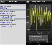
Finally test record is in house, so I can play 1kHz reference tone to see what the speed is really doing.
Not sure if I'm doing this right, but it seems consistent:
1- I measured frequency with Fluke 87 and captured peaks during 1kHz track max = 1003.9 Hz, Min =994.9 HZ. That gives 9 Hz of play, or 0.9%
2. Captured peak dancing around 1000Hz by RTA window , please look at video below. It gave me 8Hz dancing area, or 0.8 %.
At the moment stock plastic pulley from VCR is on motor and belt is too long o-ring. I think this will further improve with precision metal pulley and flat belt...
Hi Hans,
Thanks, helpful and resourceful from you as always 👍
Quickly googled Dr Feickert, seems to be paying tool, I don't have it (yet).
I measured 2 ways: simply by Fluke capturing frequency peaks and by RTA capturing 1kHz peak dancing left and right around 1kHz mark. Both gave me under 1%, so +-0,4% or very close to it. This gives me inspiration to order proper pulley and hope it will be better.
The mass of the platter/sub-chassis seems too great to cause such variance. The power/energies involved to create what you describe as "dancing" doesn't seem possible in such short periods of time. It seems more likely measurement errors. By the way, frequency errors also occur by the extent the centre hole is offset in the record.
Last edited:
Thanks Hierfi, it makes sense....
Think that Ortofon test lp is as good as lp's get, I'll still need to find way to accurately measure speed in short time interval.
My industrial mind is telling to install proper optical encoder for servo drive with several thousands of steps, but that's very complicated. Must be simpler method?
Think that Ortofon test lp is as good as lp's get, I'll still need to find way to accurately measure speed in short time interval.
My industrial mind is telling to install proper optical encoder for servo drive with several thousands of steps, but that's very complicated. Must be simpler method?
I'm getting very confused. It is fist time I have test record and TT connected to RTA and results that Im getting are just disappointing... For time I suspected my preamp is bad, to check I did something very unsafe; plugged cartridge directly to RME microphone preamp. With a click of mouse I can send 48 Volts phantom power to my 2000 € chart... so I thought few times before doing it...Anyway it is done, and my preamp is not wrong at all, results with RME mic amp are the same, and horrifying. I was thinking to post this for couple of days, but now I see it is not mistake in measuring (I measured successfully 0.000xx THD amps)
1kHz from test record:

Sweep 800Hz - 50kHz before RIAA!!! Nota bene: pls forget trace after 20 some khz, that's system issue.

Correct and "wrong" channel. The lower trace is from channel that doesn't have recording. Here at least we have -38db separation while spec of my chart is "better than 35db channel separation".

These measurements are worst then when doing loudspeakers, almost.... I always knew that 2 electro mechanical components (cartridge and speakers) are the worst for reproduction and in need of most care,
But these results shows that or that my cartridge is garbage (and is not, music plays beautifully from it) or that LP's should rally be recycled, or that distortion doesn't matter, or that I'm lost! (likely there is more than one truth in those statements).
Frankly I never seen such measurements, as I have never seen measurements of turntable on Real Time Analyzer ...
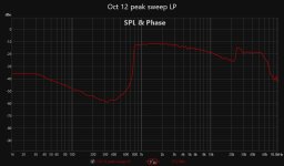
1kHz from test record:
Sweep 800Hz - 50kHz before RIAA!!! Nota bene: pls forget trace after 20 some khz, that's system issue.
Correct and "wrong" channel. The lower trace is from channel that doesn't have recording. Here at least we have -38db separation while spec of my chart is "better than 35db channel separation".
These measurements are worst then when doing loudspeakers, almost.... I always knew that 2 electro mechanical components (cartridge and speakers) are the worst for reproduction and in need of most care,
But these results shows that or that my cartridge is garbage (and is not, music plays beautifully from it) or that LP's should rally be recycled, or that distortion doesn't matter, or that I'm lost! (likely there is more than one truth in those statements).
Frankly I never seen such measurements, as I have never seen measurements of turntable on Real Time Analyzer ...
Attachments
Is this the Ortofon test disk ?
You should play the square wave with Riaa correction.
Be be aware that Riaa also slightly attenuates the harmonics, but 1% H2 at 1Khz and 0dB is quite normal.
Isn’t it amazing how fantastic it can sound despite the relatively large THD?
Hans
P.s. Crosstalk is very good for a Cart
You should play the square wave with Riaa correction.
Be be aware that Riaa also slightly attenuates the harmonics, but 1% H2 at 1Khz and 0dB is quite normal.
Isn’t it amazing how fantastic it can sound despite the relatively large THD?
Hans
P.s. Crosstalk is very good for a Cart
Drbulj,
I can imagine that those plots are confusing you a lot.
One reason is because the Ortofon test disk is very confusing and support from Ortofon is zero when asking them for help.
1) The SPL plot only starts to be valid as from 2Khz.
From there it goes down with 10dB/decade up to 40Khz and not the 50Khz they mention.
So to get a better view on your Cart’s FR, draw a line with a 10dB/dec through the plot starting at 2Khz.
Later today I’ll send you some samples.
However, the one thing I don’t get is why your A/D converter makes this strange jump above 20Khz. Have you any idea why ?
2) The square wave on the LP is also very strange. It is recorded with Riaa correction and for some reason it has an uncommon duty cycle.
I found this LP and the complete lack of support from Ortofon very frustrating and because of that not worth the €50,- they charge for it.
Hans
P.s. later today I’ll send you my recordings for you to compare.
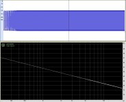
Here you are.
First image is a logarithmic sweep, top the time signal showing constant level, below the FR showing the 10dB/dec I mentioned.
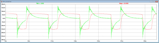
Second image showing the sweep from the Ortofon LP in 33 1/3 and 45rpm.
This proves that he anomalies starting at 40Khz when played at 33 1/3 shift upwards when playing at 45rpm, proving it's not my Cart but the test LP that is falling short as from 40Khz despite it's promise to go from 800Hz to 5Khz.
Third image shows the square with without and with Riaa Correction.
One last thing to mention is that to get reliable frequency plots, you should record tracks 1 to 4 in one go before doing the FFT processing, this gives some sort of averaging that improves the results.
The Cart I used was a Benz LP, specified as having +/-0.5dB up to 50Khz, which seems to be rather correct.
Hans
First image is a logarithmic sweep, top the time signal showing constant level, below the FR showing the 10dB/dec I mentioned.
Second image showing the sweep from the Ortofon LP in 33 1/3 and 45rpm.
This proves that he anomalies starting at 40Khz when played at 33 1/3 shift upwards when playing at 45rpm, proving it's not my Cart but the test LP that is falling short as from 40Khz despite it's promise to go from 800Hz to 5Khz.
Third image shows the square with without and with Riaa Correction.
One last thing to mention is that to get reliable frequency plots, you should record tracks 1 to 4 in one go before doing the FFT processing, this gives some sort of averaging that improves the results.
The Cart I used was a Benz LP, specified as having +/-0.5dB up to 50Khz, which seems to be rather correct.
Hans
Attachments

- Home
- Source & Line
- Analogue Source
- Fully balanced MC phono preamplifier thoughts