I've seen a mod for the crescendo from 1982 where a 0.5mm2 wire is soldered on the bigger traces.
Was there a problem with th original PCB layout and what if the PCB layout was okay, what is the benefit of this mod?
Was there a problem with th original PCB layout and what if the PCB layout was okay, what is the benefit of this mod?
Hi there,
I' build this amp in 1996 and done a couple of rebuilds later on.
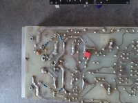
PCB tracks were rather small, like 2mm in the output stage. Adding a wire increases current capability and thus lowers temperature increase of pcb tracks.
Lateral mosfets can still be purchased at Profusion PLC. Make sure you use low-inductance source resistors, this amp was very very sensitive for this, oscillation was triggered easily.
I' build this amp in 1996 and done a couple of rebuilds later on.
PCB tracks were rather small, like 2mm in the output stage. Adding a wire increases current capability and thus lowers temperature increase of pcb tracks.
Lateral mosfets can still be purchased at Profusion PLC. Make sure you use low-inductance source resistors, this amp was very very sensitive for this, oscillation was triggered easily.

So I could use the MPC-71 types for the 0.22 ohm resistors?
Another question:
Are the BC546A and BC556A in the differential stage still a good choice or can the be replaced with more modern equivalents?
Another question:
Are the BC546A and BC556A in the differential stage still a good choice or can the be replaced with more modern equivalents?
Should be possible yes. For matched BJT output stages, 5% tolerance would be a NoGo, for lat fet’s no real issue.
A goto small power bjt is 2240/979, however also obsolete now. 992/1845? The BC’s are not real low noise, while highish rbb.
A goto small power bjt is 2240/979, however also obsolete now. 992/1845? The BC’s are not real low noise, while highish rbb.
If build several of these, both full and mini version. All worked problem free without modification. As mentioned above low-inductance source resistors are important.
https://drive.google.com/file/d/12DSqVZyBMF8U0p4ZIbOwR7hmpkrAMG6d/
https://drive.google.com/file/d/12DSqVZyBMF8U0p4ZIbOwR7hmpkrAMG6d/
The original PCB's Elektor sold more than 40 years ago featured traces of 70 µm thickness. Not that usual to get raw material with this property. Perhaps the modification corrected it?I've seen a mod for the crescendo from 1982 where a 0.5mm2 wire is soldered on the bigger traces.
Was there a problem with th original PCB layout and what if the PCB layout was okay, what is the benefit of this mod?
Best regards!
I'd be a bit careful with arbitrary modifications like that unless you have the skills and tools to address the stability issues that can result from such modifications.Are the BC546A and BC556A in the differential stage still a good choice or can the be replaced with more modern equivalents?
Tom
I had a look at the schematic and building instructions. +-75 Volt seems very high for only two MOSfet's per side. At least I do not expect the amp to be very robust. Not the amp to play around with, more suited to be used in a fixed installation like an active speaker, where nothing unusual like a short can happen.
Maybe driving the pre stages with a high voltage and reducing the power stage voltage would be an option. Also saving a few € on PS capacitors.
Increasing the power satges PCB lines with some soldered on copper wire was often done to improve the damping factor of amps. For example such that were given to reviewers...
Take a look here http://www.raylectronics.nl/index_en.html There are a few advices to the Crescend Amp. Left Side p1-p3
I have built the smaller Amp, the Mini Crescendo. The Zobel Network with 22nf is not okay. Better use 100nf, than the Amp gets stable. Used 2SC2240/2SA970, BC550/560, MJE340/MJE350, 2SK135/2SJ45,
Two 22k resistors T8/T10, collector to ground are helpful. One 100nf capactor to the pot. I had ordered non inductiv 0,2 ohm resistors at Aliexpress, MPC-071 0,22 ohm also will be ok. I isolated one transistor pin to use 2SC2240/2SA970 (for safety).
If using the old PCB its ok to put more solder on the tracks at the output. 35 µm are ok then. Dont forget the two capacitors 330/33pf at the 2SK135 or 2SK1058.
Good Luck
Peter
Peter if i understand correctly for the mini-crescendo it's 2SC2240/2SA970 instead of the BC546B/BC556B for T1...T6, BC550/560 for T7 and T9, MJE340/MJE350 instead of BF469/BF470 for T8 and T10. Are these drop in replacements or do other components have to be altered?
How is the 100nF to the pot connected? And how are the 2 capacitors connected 330/33pf at the 2SK135?
How is the 100nF to the pot connected? And how are the 2 capacitors connected 330/33pf at the 2SK135?
^^ The mini Crescendo from 1984 is almost identical to the original from 1982. It uses BC546B and BC556B for the LTP. BC560C + BF469 and BC550C + BF470 for the cascode's.
https://drive.google.com/file/d/1ChI6oljhHZUDSlo3gHUZfZ8QJBvsPfHS/
https://drive.google.com/file/d/1ChI6oljhHZUDSlo3gHUZfZ8QJBvsPfHS/
Last edited:
Yes, with the exception of only one power device pair instead of two and the lower supply voltages. And Elektor apparently had learned something as the opted to replace the 0.22R wire wound source resistors by five paralleled 1R carbon compound ones.
Best regards!
Best regards!
Good Morning....
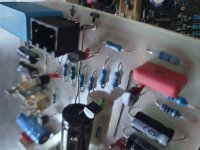
At SK135 or 2SK1058 solder between the drain and the gate 33pF , and between the source and the gate 330pF ceramic capacitor. At the pot the polyester cap 100nf is parallel.
MJE340/350 as driver transistors sound a little bit better...
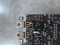
2SC2240/2SA970 have a better hFE consistency as the BC types. I think you can choose other transistors, but BC and 2SC/2SA are tested. On picture 4 you can see the isolated transistorpins.
Aaah...instead of two capacitors i have built in one bipolar type 100 uf in the feedback area.
Instead of the 3,9 volt zener diodes i solder two red led with 1,9xx Volt in. By twenty or more 3,9 volt zener diodes i could not find two equal ones....
You can read about all Mods ore changes at ray's page, exept the led mod. In the beginning my Mini Crescendo was oscilating and let get the zobelresistor up in smoke, but only at 4 ohm speakers. After a few trys i changed the Zobel capacitor from 22nf to 100nf.
Ray has confirmed that, but i found his site later. I was proud to figure it out by myself... my electronic knowledge is not so big...🙂
I built a new Mini Crescendo, but not tested yet...have to do...
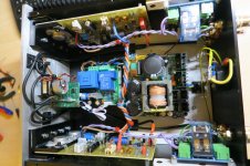
My older Mini Crescendo is powerd with a connex smps 500 W, +-48,7 Volt, got a remote for the volume and on/off. Years ago...today i would never do so again....in the past i needed a volume pot, because my Amps were connected directly to my pc soundcard. I have built different preamps now and a pot in an amp is no more necessary.
Greets
Peter
At SK135 or 2SK1058 solder between the drain and the gate 33pF , and between the source and the gate 330pF ceramic capacitor. At the pot the polyester cap 100nf is parallel.
MJE340/350 as driver transistors sound a little bit better...
2SC2240/2SA970 have a better hFE consistency as the BC types. I think you can choose other transistors, but BC and 2SC/2SA are tested. On picture 4 you can see the isolated transistorpins.
Aaah...instead of two capacitors i have built in one bipolar type 100 uf in the feedback area.
Instead of the 3,9 volt zener diodes i solder two red led with 1,9xx Volt in. By twenty or more 3,9 volt zener diodes i could not find two equal ones....
You can read about all Mods ore changes at ray's page, exept the led mod. In the beginning my Mini Crescendo was oscilating and let get the zobelresistor up in smoke, but only at 4 ohm speakers. After a few trys i changed the Zobel capacitor from 22nf to 100nf.
Ray has confirmed that, but i found his site later. I was proud to figure it out by myself... my electronic knowledge is not so big...🙂
I built a new Mini Crescendo, but not tested yet...have to do...
My older Mini Crescendo is powerd with a connex smps 500 W, +-48,7 Volt, got a remote for the volume and on/off. Years ago...today i would never do so again....in the past i needed a volume pot, because my Amps were connected directly to my pc soundcard. I have built different preamps now and a pot in an amp is no more necessary.
Greets
Peter
Attachments
Last edited:
Would it be a possibility to have the tracks that need to be thickened run on both top and bottom layer, increasing the amount of copper by 2? (or do you still end up short)?
Would these create a capacitance problem? (don't think so since they are carrying the same signal)?
Would these create a capacitance problem? (don't think so since they are carrying the same signal)?
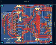
You can order 2oz thickness, thats 70µm exactly. At JLCPCB its possible. I think only the driver section and output must be thicker. If you decide to make a new pcb you can choose more mm/inch for the tracks. I haven choosen 3 mm tracks to the 0,2 ohm resistors (very short) and voltage rails (more is possible). The driver section has 2 mm. Thats much more as on the original pcb.
I you want more safety for capacitance, you can make the tracks as broad as possible if there is space enough. My output secktion has 7,45 mm. I wanted a smaller pcb.
I think the problems, if a Crescendo Amp dos not work correctly, has other reasons, not the pcb...
Greets
Peter
I you want more safety for capacitance, you can make the tracks as broad as possible if there is space enough. My output secktion has 7,45 mm. I wanted a smaller pcb.
I think the problems, if a Crescendo Amp dos not work correctly, has other reasons, not the pcb...
Greets
Peter
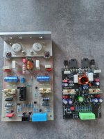
Your black PCB looks neat. Has the driver enough power to control 2x4 MOSfet's? If yes you could use 2x ECW20P20 and 2x ECW20N20 and have twice the current ability. The problem with the driver stage was it's ability to drive the voltage fast enough to the gate, which is a small capacitance. If the driver was too weak, you got the typical "MOSfet sound" that is criticized so often. Designers did wrong because the parts were said to be voltage driven, which was only half the truth.
The Profusion production is said to have less oscillation problems due to improved chip construction. My amps (not ELEKTOR) did not need any extra capacity at the MOSfet legs and oscillation was never a problem. Would be interesting to put the ELEKTOR design into Spice and find out where they messed up. I know the Elektor designs to have problems, depending on different parts used, which points to something in the design running “at the edge”. A simulation could find out where the problem is located.
Interesting is, that at Profusion.UK the transistors are less expensive than 30 or more years ago at Albs, GM Klein and how they were called.
If you need the old metal can TO3 it is last call now. They are end of life and only a few left. You can be sure they get ridiculous expensive very soon.
https://gb.profusion.uk/uk/audio/transist/lateral-mosfets
- Home
- Amplifiers
- Solid State
- Crescendo 1982 PCB-copper thickening