Hi, hoping to get your thoughts on a simple pre-amp design using the 317A tube. I don't need much gain. Looking to add some tube sonic flavor. Source is a streamer (600ohm output, 2Vrms). Amp is solid state with 10K input impedance.
A few specific questions on the schematic:
1. Is the 1 uF cap sufficient? I don't need much below 30hz.
2. Is the OD3 tube regulator necessary? Will it improve sound?
3. I have read quite a bit on AC vs DC filaments. I would like to try AC from a simplicity perspective. Any issues with this?
4. The autoformer is at the input, instead of output. Sound ok?
Looking forward to your input/guidance.
Attachments
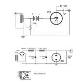
That schematic has Major problems.
Where did you get the schematic?
The Western Electric 371A is a rectifier.
It is Not a triode amplifier.
Since there is no triode grid to control current, the 371A will draw excess current, and power transformer, bridge rectifier, and 371A may be destroyed.
The OD3 . . . There is no series resistor from C2 to the OD3.
If the 371A fails open from the excess current, then the OD3 will overheat, and crack, or even explode.


Who makes this tube? It's pretty unusual to google something like this and get zero hits.The CX-371A is a DHT.

jeff
People usually call that tube a "71A".
The CX-371A was Cunningham's version.
Is that a battery in series with the grid? If so, remember that an autoformer does not block DC. That's not the way I'm used to seeing fixed bias done using a battery. This is what I'm used to seeing, but a coupling cap would be necessary before Rg and the 4V battery:
![bias[1].gif](https://www.diyaudio.com/community/attachments/bias-1-gif.1334145/ "bias[1].gif")
With a directly heated triode (DHT), the cathode is the heater. They are one and the same. Superimposing 5VAC on the cathode will very likely result in too much hum heard in the output from the plate, unless you have a really clever way of wiring the AC heater supply. That's why everybody's using DC supplies for their DHT heaters, usually the Rod Coleman ones.
Look up what member andyjevans has done with DHT line stages. He's tried a bunch of different tubes including 26, 4P1L, 2A3, etc.
The CX-371A was Cunningham's version.
Is that a battery in series with the grid? If so, remember that an autoformer does not block DC. That's not the way I'm used to seeing fixed bias done using a battery. This is what I'm used to seeing, but a coupling cap would be necessary before Rg and the 4V battery:
With a directly heated triode (DHT), the cathode is the heater. They are one and the same. Superimposing 5VAC on the cathode will very likely result in too much hum heard in the output from the plate, unless you have a really clever way of wiring the AC heater supply. That's why everybody's using DC supplies for their DHT heaters, usually the Rod Coleman ones.
Look up what member andyjevans has done with DHT line stages. He's tried a bunch of different tubes including 26, 4P1L, 2A3, etc.
Ah, ok thanks. Maybe @rayma could fix the thread title, cause it's obviously incorrect. 🙂People usually call that tube a "71A".
The CX-371A was Cunningham's version.
jeff
The B+ is probably well filtered enogh, and well regulated enough for a preamp stage.
But using a DHT as a preamp, and with ACpowered filaments is just waiting . . . . to annoy you with lots of hum.
Just my $0.03
But using a DHT as a preamp, and with ACpowered filaments is just waiting . . . . to annoy you with lots of hum.
Just my $0.03
The way people are using DHTs as line stages is using Rod Coleman's DC filament supplies and filamentary bias. They apparently work very well (a friend of mine builds stuff with DHTs on a regular basis and he's sold on the Rod Coleman filament supply).
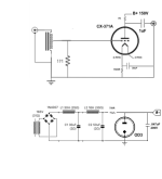
OK, good input people. Thank you. I get your point about AC filament, so the schematic now reflect DC filament with cathode bias (20mA). Also, a plate resistor of 750R was added to draw the 20mA of current. The 30uF cathode cap is using the ultrapath topology.
I am still not sure / convinced if the tube voltage regulator (OD3) is necessary.
I am still not sure / convinced if the tube voltage regulator (OD3) is necessary.
Attachments
This might serve as inspiration: https://i0.wp.com/www.bartola.co.uk/valves/wp-content/uploads/2021/02/CX371a-preamp-V6.jpg?ssl=1
You could use SMPS, both for filament and HT (easier & cheaper).
Re your question 1: https://www.v-cap.com/coupling-capacitor-calculator.php
You could use SMPS, both for filament and HT (easier & cheaper).
Re your question 1: https://www.v-cap.com/coupling-capacitor-calculator.php
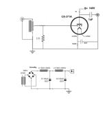
I would use choke input power supply as shown with Cree (Schottky) 600 volt no noise rectifier or a Mullard EZ80 or EZ81 tube rectifier. The regulator tube is unnecessary and can add noise. 1uF is slow to discharge, I would use .1uF coupling capacitor. Russian K40Y-9 is about as good as it gets for quality sound.
Update schematic per everyone's input.
Isn't 0.1uF too small and will reduce low end output?1uF is slow to discharge, I would use .1uF coupling capacitor.
Attachments
The 30uF cathode cap is using the ultrapath topology.
Actually, no it's not. It's connected from cathode to ground, the usual way. Ultrapath connection would put the 30uF cap from cathode to B+ (and would inject any AC noise on the B+ into the cathode of the DHT, which could be interesting!).
Isn't 0.1uF too small and will reduce low end output?
Yes, it probably would be too small, depending on the load impedance this preamp would drive. Will this line stage be driving a tube amp, or a solid state amp?
Another hidden aspect is that a very small value capacitor there would present a high impedance at low frequencies, which could result in hum pickup from cables connecting from the line stage output to the load (power amplifier).
I would put a 'pulldown' resistor from after the cap to ground (an output load resistor). Something like 100k to 1M ohms is the usual choice. There are upsides and downsides to lower or higher values.
Last edited:
Yes, that is an autoformer volume control.
This will be driving a solid state amp with 10K input impedance. 3 feet cables.
Regarding the 1uF cap vs. .01uF vs. 22uF. Is there a rule of thumb or calculation to determine the "proper" value?
If 1uF and 1M are used as in the updated the schematic, this gives a 8Hz rolloff assuming the power amp 10K input impedance.
Attachments
Last edited:
Regarding the 1uF cap vs. .01uF vs. 22uF. Is there a rule of thumb or calculation to determine the "proper" value?
F3 = 1/2piRC (C in microfarads)
The usual goal is to get the F3 down below about 2Hz or so, so there is no attenuation at 20Hz (the bottom end of the audible frequency range). That's not a requirement, but it is the usual goal.
Figure that if F3 = 8Hz then there will be some attenuation at 80Hz and lower. Many would say that's not truly 'full range', but if that goes low enough for you, then it's good.
However, if this preamp will be driving a solid state amp, you don't want the preamp to dump hundreds of volts into the input of the solid state amp as the tube stage's output cap charges up. You want the time constant to be as short as possible so the capacitor charges up quickly. But you want the time constant to be as long as possible so bass frequencies pass through unattenuated and with minimal phase shift. Those two goals are mutually exclusive, so you have to decide on a workable compromise.
Nothing is perfect.
Everything is a compromise.
Thanks rongon, very helpful. I will start with 1uF, as it appears to be a decent starting point and I have a very nice pair of 1uF caps that need to be utilized 🙂. I can always "cap roll" to see which I like.
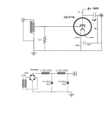
team - a couple other questions:
1. what are you thoughts on running the cathode bypass cap to B+ instead of ground, thus following a Ultrapath topology?
2. In your experience, will the sonics improve by replacing the 7K plate resistor with a plate choke?
team - a couple other questions:
1. what are you thoughts on running the cathode bypass cap to B+ instead of ground, thus following a Ultrapath topology?
2. In your experience, will the sonics improve by replacing the 7K plate resistor with a plate choke?
I would wire it up point-to-point (don't bother with any PCB). The circuit is so simple, it should be pretty easy to do.
Leave lots of room so you can experiment.
Try the Ultrapath cap connection. Compare to the standard Ck connection to 0V. Tell us if you hear a difference.
Have you plotted any load lines for your proposed circuit? How did you settle on 7k ohms for Rp?
My opinion - A '71A all by itself will load down some into a solid state amp input with 10k ohm load impedance. I would choose a smaller tube (could be a low mu DHT like a 26) and DC couple its plate to a MOSFET source follower as a buffer. That would give you the sound of the DHT and the low impedance needed to easily drive the heavier 10k load impedance of the solid state amp. Tubes are high impedance, transistor circuits work at much lower impedances. The buffer bridges the gap between the two worlds.
A plate choke would improve that situation a little. Not as much of an improvement as a source follower, though.
That's my opinion, though. There are those who disagree. That's fine.
- Home
- Amplifiers
- Tubes / Valves
- 71A preamp design