After a long time as a spectator, I'm starting a line source project. The driver parameters measured in REW are the following:
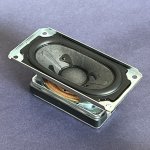
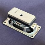
They are Sony almost oval TV drivers and measures approximately 105mm x 50mm or 4 1/8” x 2”. With the parameters, I defined a volume of 2 liters per driver because increasing the volume has little impact on the response. As illustrated in the above image, the active area of the speaker measures 82mm x 39mm.
In VituixCAD, should I simulate it as a circular driver with Dd=82mm (largest vertical dimension) or as a rectangular driver with Height=82mm and Width=39mm?
Update:
Later, in post #50, I demonstrate that these first simulations were wrong.
In short, in the diffraction tool (F4), place only one driver. From the data obtained from this driver, the program simulates the results for the arrangement of the various drivers that you place in the driver layout tool.
They are Sony almost oval TV drivers and measures approximately 105mm x 50mm or 4 1/8” x 2”. With the parameters, I defined a volume of 2 liters per driver because increasing the volume has little impact on the response. As illustrated in the above image, the active area of the speaker measures 82mm x 39mm.
In VituixCAD, should I simulate it as a circular driver with Dd=82mm (largest vertical dimension) or as a rectangular driver with Height=82mm and Width=39mm?


Update:
Later, in post #50, I demonstrate that these first simulations were wrong.
In short, in the diffraction tool (F4), place only one driver. From the data obtained from this driver, the program simulates the results for the arrangement of the various drivers that you place in the driver layout tool.
Last edited:
I continued simulating as rectangular drivers.
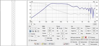
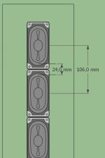
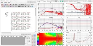
With 20 of them arranged vertically in a line, with 106mm c-t-c because of the edges, without equalization, filters or power shading, the resulting graphics were these:

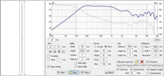
To reduce the c-t-c distances to the same dimension as the vertical length of the cone (82mm), I arranged 25 drivers alternately. The SPL graph improved and the vertical directivity graph was surprising:
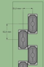
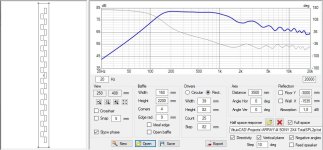
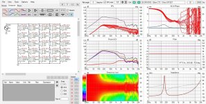
From the graphs, the offset configuration presents the best preliminary results. I didn't expect that. Has anyone ever tested something like this? What are the pros and cons?
With 20 of them arranged vertically in a line, with 106mm c-t-c because of the edges, without equalization, filters or power shading, the resulting graphics were these:


To reduce the c-t-c distances to the same dimension as the vertical length of the cone (82mm), I arranged 25 drivers alternately. The SPL graph improved and the vertical directivity graph was surprising:


From the graphs, the offset configuration presents the best preliminary results. I didn't expect that. Has anyone ever tested something like this? What are the pros and cons?
Very interesting - I have pondered an horizontal offset myself for a build with a bit larger driver - say 4-5" (round) but never did a simulation. We could say that this is a quite a substantial improvement - I wonder what @wesayso would say? 😉

//
//
In the sims, you just decreased the c-t-c, but haven't taken into account the offset of the c-t-c (and I'm not familiar enough with the apps to try and simulate that, if even possible). So, of course, we see a lot less comb filtering at 82mm, instead of 106mm.
Also, wouldn't the c-t-c be the diagonal between the drivers?
Again, way over my head regarding simulations of offset drivers in a line.
Also, wouldn't the c-t-c be the diagonal between the drivers?
Again, way over my head regarding simulations of offset drivers in a line.
Judging by the pics, it looks like OP did factor in the offset? I'm not too savvy with VCAD though, so I might be mistakenIn the sims, you just decreased the c-t-c, but haven't taken into account the offset of the c-t-c
Good observation @perceval , but there is a layout tool in VituixCAD to define driver positions. The distance was 80 mm so I corrected it to 82 mm, as I mentioned, and the result is still very good.

80mm c-t-c:

82mm c-t-c:

80mm c-t-c:
82mm c-t-c:
that clears it up, thanks. Learned a bit more about VituixCAD.
If you wanted to really cut the c-t-c distance, you could place the drivers horizontally instead of vertically, but that means you will need a lot more drivers to achieve the 75% coverage between floor and ceiling to get mirror images. And a lot more work for wiring them up! 🙂
If you wanted to really cut the c-t-c distance, you could place the drivers horizontally instead of vertically, but that means you will need a lot more drivers to achieve the 75% coverage between floor and ceiling to get mirror images. And a lot more work for wiring them up! 🙂
I continued simulating as rectangular drivers.
With 20 of them arranged vertically in a line, with 106mm c-t-c because of the edges, without equalization, filters or power shading, the resulting graphics were these:
View attachment 1327422View attachment 1327415 View attachment 1327405
To reduce the c-t-c distances to the same dimension as the vertical length of the cone (82mm), I arranged 25 drivers alternately. The SPL graph improved and the vertical directivity graph was surprising:
View attachment 1327423View attachment 1327414 View attachment 1327407
From the graphs, the offset configuration presents the best preliminary results. I didn't expect that. Has anyone ever tested something like this? What are the pros and cons?
Interesting results for the vertical directivity! 🙂 I was wondering about the horizontal results, but that doesn't look all that great?
Usually, the horizontal is pretty close to the directivity graph of a single driver (for a single row of drivers in an array). So I can't quite follow what's happening here?
The vertical directivity looks great in comparison. If I find the time I'll run some sims with the TC9 out of curiosity.
It makes sense, but in the layout tool the "C-C dist" field only refers to the vertical distance between the drivers and the "X mid" field, which I called offset, only refers to the horizontal position.Also, wouldn't the c-t-c be the diagonal between the drivers?
I don't mean to sidetrack this thread, but I've a question about oval drivers like these. Why do some of them have rectangular magnet structures like the ones shown here? When a company that spends on research, like Sony does, uses them, there must be a good reason. Are they trying to increase the magnetic strength in the VC gap, aligned with the shape of the cone, so that the voice coil pushes harder on the higher mass parts of the cone? I'm curious! Cheers, Dave
Maybe they need to fit the maximum magnet volume into a shape that can be inserted into a barrow baffle opening?rectangular magnet structures
Just spitballing, but it might be just for ease of installationI don't mean to sidetrack this thread, but I've a question about oval drivers like these. Why do some of them have rectangular magnet structures like the ones shown here? When a company that spends on research, like Sony does, uses them, there must be a good reason. Are they trying to increase the magnetic strength in the VC gap, aligned with the shape of the cone, so that the voice coil pushes harder on the higher mass parts of the cone? I'm curious! Cheers, Dave
It might be installation, but in most of the oval speaker/round magnet types I've seen, the magnet has still been less than the width of the narrow part of the oval... Anyway, as I say, I don't mean to hijack this thread, it's just something I'm curious about!
It is probably quite easy and cheap to manufacture a circular magnet, and it is probably quite easy and cheap to manufacture a square/rectangular magnet. An ovular magnet on the other hand, I would assume is fairly more expensive and difficult to produce. So, by my guestimation, size constraints + ease of installation + cost to manufacture = rectangular magnet. I would be astonished if they arrived at that shape for sound quality reasons, for something like a TV speakerIt might be installation, but in most of the oval speaker/round magnet types I've seen, the magnet has still been less than the width of the narrow part of the oval... Anyway, as I say, I don't mean to hijack this thread, it's just something I'm curious about!
Yes, it is an option. 42 drivers would be needed per column. I gain in frequency response because the cancellations will start at a higher frequency, but I lose in horizontal dispersion compared to drivers mounted vertically, with a narrower profile. I will simulate, compare and rely on your opinion and experience before spending time and money on MDF and assembly.If you wanted to really cut the c-t-c distance, you could place the drivers horizontally instead of vertically
Dispersion can be improved with toe in, frequency response cannot. But it has its price.
Last edited:
- Home
- Loudspeakers
- Full Range
- Oval driver line source

