Prob not. They seem to be the same diameter but about 4/5 long with screw terminals.
I would have to wire them, which would be easy enough even if not pretty.
I would have to wire them, which would be easy enough even if not pretty.
Got my kit today, now comes the hard part of patiently waiting for my chassis to get here.
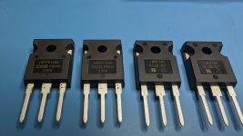
Looks like this batch has IR for the P channel instead of Harris like the first batch had.
Looks like this batch has IR for the P channel instead of Harris like the first batch had.
multiple Milf in this position is always better 😀
Brilliant suggestion.

Quite some of you have built the F5M already and some of you have also available the original F5 (may be without output limiter and Th1 and Th2) or a version of F5 Turbo. Can you please describe the sonic differences between the various F5's? Is it worth building an F5M (due to less parts) ?
@xt0rted - Could you take a quick photo of the parts, please?Got my kit today, now comes the hard part of patiently waiting for my chassis to get here.
Looks like this batch has IR for the P channel instead of Harris like the first batch had.
Yes, faced with multiple milfs, MZM will be hard pressed to sleep.multiple Milf in this position is always better 😀
learn from ZM ,is never sleep
I have a few reels of Harris 240s and 9240s, if anyone feels an itch I can match some up.
… Is it worth building an F5M …
Yes
The supplied parts are fine. We are using IRF140 and 9140 which do not have the issues found in the IR version of the IRF9240, which is a shift in transconductance value at midrange frequencies.
Good to hear. Essentials kit came in the post today, Digikey per NP's BOM due Tuesday. Oversized surplus heat sinks from another member here on the swap page, ~ 3x by volume vs. the 3U option in the R.1 article. Ordered some raw material cut to size chassis parts from Metals Depot, first try with them, will report results. AS-4218 ordered, plan for two bridge rectifiers for least noise. Switch, fuse holder, binding posts are available spares. Therefore, deem it
Fugly 5ive maximinimalist
It will be a good summertime option
Hi all,
Since I am a novice I'd like to verify wiring of secondaries using one bridge rectifier. Is the attached drawing correct? Transformer is an Antek AS-4218.
Also, what are the recommended fuses? 10 amp slow blow for N and 2 or 3 amp slow blow for L?
Thanks.

Since I am a novice I'd like to verify wiring of secondaries using one bridge rectifier. Is the attached drawing correct? Transformer is an Antek AS-4218.
Also, what are the recommended fuses? 10 amp slow blow for N and 2 or 3 amp slow blow for L?
Thanks.
Last edited:
@bentconvert
I am assuming you are using an IEC inlet fuse holder like the Schurter types supplied with the diyaudio deluxe chassis.
If both the hot and neutral wires are fused, for safety, the neutral fuse should be higher current capacity so that in the event of a fault, the hot fuse will blow. If the neutral blows instead, the hot line is still live and there is still electricity in the chassis which is dangerous. Therefore the neutral fuse should be a high value like 10A slow blow in your example and the line fuse (hot) should be VA of transformer divided by 120V. For example 300VA transformer/120V = about 2-3A.

Identifying the primary and secondary windings is important and you should use your DMM to assist.
For 120V line input as you probably have in the US, connect wires 2 and 4 together (Red colors), this connects to your “hot” or ”line”. Connect wires 1 and 3 (Black colors) together and these become your “neutral”. This should be easy.
For secondary wire identification, pull out your multimeter or DMM and check to make sure you identify the secondaries that have continuity (0 ohms on the resistance setting). Wire 5 and 6 should have continuity, similarly, wire 7 and 8 should have continuity. You can double check this and also make sure that wires 5 and 8 do not have continuity and read infinite. Similarly wires 6 and 7 should not have continuity.
Wires 6 and 7 are your ‘CENTER TAP’ and should be connected together as you have shown in your schematic diagram which is also connected to power supply ground and to the thermistor that is acting as a ground lift to chassis ground.
Although all the colors of the wires should match with the above pic, do note that you need to use your DMM to properly identify the secondaries here since you cannot distinguish wires 6 and 7 by color identification alone or by the location of the wires on the transformer itself.
Hope this helps,
Anand.
I am assuming you are using an IEC inlet fuse holder like the Schurter types supplied with the diyaudio deluxe chassis.
If both the hot and neutral wires are fused, for safety, the neutral fuse should be higher current capacity so that in the event of a fault, the hot fuse will blow. If the neutral blows instead, the hot line is still live and there is still electricity in the chassis which is dangerous. Therefore the neutral fuse should be a high value like 10A slow blow in your example and the line fuse (hot) should be VA of transformer divided by 120V. For example 300VA transformer/120V = about 2-3A.
Identifying the primary and secondary windings is important and you should use your DMM to assist.
For 120V line input as you probably have in the US, connect wires 2 and 4 together (Red colors), this connects to your “hot” or ”line”. Connect wires 1 and 3 (Black colors) together and these become your “neutral”. This should be easy.
For secondary wire identification, pull out your multimeter or DMM and check to make sure you identify the secondaries that have continuity (0 ohms on the resistance setting). Wire 5 and 6 should have continuity, similarly, wire 7 and 8 should have continuity. You can double check this and also make sure that wires 5 and 8 do not have continuity and read infinite. Similarly wires 6 and 7 should not have continuity.
Wires 6 and 7 are your ‘CENTER TAP’ and should be connected together as you have shown in your schematic diagram which is also connected to power supply ground and to the thermistor that is acting as a ground lift to chassis ground.
Although all the colors of the wires should match with the above pic, do note that you need to use your DMM to properly identify the secondaries here since you cannot distinguish wires 6 and 7 by color identification alone or by the location of the wires on the transformer itself.
Hope this helps,
Anand.
Well I have a "mark 1" F5 that is about 15 years old now, in the end I found it a bit too strident and unforgiving with some material. The F5M changes that and is superbly balanced and detailed without ever going ott. It simply has a magic sparkle to the sound!! I prefer the bias at 1.1 so no need for massive heatsinks if that's a consideration for you. Go for it!!Quite some of you have built the F5M already and some of you have also available the original F5 (may be without output limiter and Th1 and Th2) or a version of F5 Turbo. Can you please describe the sonic differences between the various F5's? Is it worth building an F5M (due to less parts) ?
captain pugwash,
What is the heatsink / chassis size for your build?
For speakers, you are using a single wide band driver (MA Alpair)?
What is the heatsink / chassis size for your build?
For speakers, you are using a single wide band driver (MA Alpair)?
Chassis is a 4U (I reused my F5 chassis and transformer so life was easy but knowing 1.1amp bias was good for me I would get something smaller if building another).
Speakers are Alpair 10P in a MLTL and TABAQ with PLS-P830987, both sound superb with the F5M .
Speakers are Alpair 10P in a MLTL and TABAQ with PLS-P830987, both sound superb with the F5M .
Well I have a "mark 1" F5 that is about 15 years old now, in the end I found it a bit too strident and unforgiving with some material.
Did you have the current limiting circuits installed?
Not aware of what this is so I guess no!, my build was as per the original build guide from 2008.Did you have the current limiting circuits installed?
- Home
- Amplifiers
- Pass Labs
- F5m kit