Hi, I am in the process of rebuilding a pair of John Bowers Active Ones.
All seems fine so far, apart from a slightly high DC offset of 130mV on one of the boards.
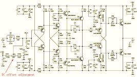
There is no adjustment preset for DC offset, and I am wondering if anyone could advise me on the possibility of adding a DC offset adjustment preset to the Amplifier Board?
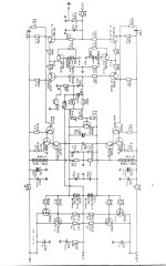
I have attached the circuit diagram. Any suggestions would be welcome.
All seems fine so far, apart from a slightly high DC offset of 130mV on one of the boards.
There is no adjustment preset for DC offset, and I am wondering if anyone could advise me on the possibility of adding a DC offset adjustment preset to the Amplifier Board?
I have attached the circuit diagram. Any suggestions would be welcome.
Attachments

Hi, thanks for that. I had a look at some other simar amplifier schematics to see if I could add offset adjustment to my circuit but couldn't identify a part of the pre stages where I could insert one.
I noticed your schematic adjust into the long tailed pair, but there doesn't appear to be a conventional long tailed pair in this circuit?
Clydear
I noticed your schematic adjust into the long tailed pair, but there doesn't appear to be a conventional long tailed pair in this circuit?
Clydear
Yes there are, two of them - tr301, 302 and tr305, 306.there doesn't appear to be a conventional long tailed pair in this circuit?
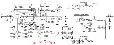
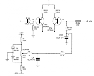
If you want to use the example posted by levinson mark in post #4, connect the "A" node from his schematic to feedback returning node (whereR309 and R320 meet) in your sch.
Hi, thanks for that. I had a look at some other simar amplifier schematics to see if I could add offset adjustment to my circuit but couldn't identify a part of the pre stages where I could insert one.
I noticed your schematic adjust into the long tailed pair, but there doesn't appear to be a conventional long tailed pair in this circuit?
Clydear
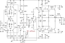
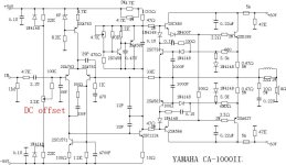
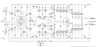
See if these methods are useful ?
Attachments
Hi Juma, many thanks for your tips.
I'm away from home at the moment but will get on to it as soon as I return.
Is there any that stand out as most suitable to adapt?
Clydear
I'm away from home at the moment but will get on to it as soon as I return.
Is there any that stand out as most suitable to adapt?
Clydear
All those methods fall into two groups:Is there any that stand out as most suitable to adapt?
1) Injecting small DC voltage into sensitive nodes (feedback or input mostly),
2) changing DC balance (by changing certain resistor's value that controls current through some transistor) in appropriate node in order to equalize DC offset at the output.
If you want unconditional precision (independence from rails' voltage variations) use DC servo method (it falls into group 1). Of course, it comes with the price of added complexity. Google for it, have look around and when you understand what and how it works, you'll know what to do...😉
Hi again, I am aware of the servo method for balancing offset.
I didn't really want to make any significant changes to original circuit, so I'll probably go with one of the methods already suggested.
Many Thanks
I didn't really want to make any significant changes to original circuit, so I'll probably go with one of the methods already suggested.
Many Thanks
Then all you need is precise hfe/Vbe selecting/matching of 4 transistors in input LTPs.I didn't really want to make any significant changes to original circuit
I did suspect that transistor matching might be the cause of the offset, but as I hadn't identified the long tailed pairs, I wasn't sure what transistors to start checking. Now armed with the extra info, I'll pull and test them.
It would be great if problem could be solved without any modifying.
It would be great if problem could be solved without any modifying.
maybe the ccs supplying those ltp's are suspect - check the volts across R307/318
did you have this issue before the rebuild?
did you have this issue before the rebuild?
Thanks for your additional tip.
I'll have an in-depth look around the ltp components and voltages when I return home.
The rebuild was mostly centred around dry joints and electrolytic capacitors. All 4 output boards are fully operational now, apart from the aforementioned offset on one of the boards. Difficult to confirm whether offset fault existed previously.
You could check the LTP and VAS transistors and also the caps in feedback path just incase somethings about to fail. Did you replace any of the transistors? What's the offset on the other? They shouldn't be too far off each other, looks like a good amplifierHi, I am in the process of rebuilding a pair of John Bowers Active Ones.
All seems fine so far, apart from a slightly high DC offset of 130mV on one of the boards.
There is no adjustment preset for DC offset, and I am wondering if anyone could advise me on the possibility of adding a DC offset adjustment preset to the Amplifier Board?
I have attached the circuit diagram. Any suggestions would be welcome.
Just incase the VCEO of the LTP BC556B and BC546B was exceeded try replace these first with similarly matched parts
Armed with all the info you guys have given me, I'm looking forward to getting it back on workbench and resolving the problem. I'll keep you updated.
Thanks to all.
Thanks to all.
Hi, just a quick update. I pulled the transistors you suggested I check in previous post. I found N and P pairs pretty well matched between them, but not matched from P to N. The N side have gains of around 250, the P side has gains of below 90. All else checks out ok although I did note that R338 measured 15 ohms and should have been 12. Nothing else found. I've ordered a quantity of BC546 and 556, plus I already have a few to add so I can select some close matched pairs across the P side and N side.
130mV seems like a lot of offset with C305 in the circuit.
if you matched up the input stage diff amp transistors, you might want to see if C305 is leaky or otherwise defective,
including cleaning any electrolyte if it spilled any.
i'd check that before trying to dial in some kind of offset voltage ...
if you matched up the input stage diff amp transistors, you might want to see if C305 is leaky or otherwise defective,
including cleaning any electrolyte if it spilled any.
i'd check that before trying to dial in some kind of offset voltage ...
- Home
- Amplifiers
- Solid State
- John Bowers Active One Amplifier Boards