Hi All.
Sorry for my absence from the forum.
Had been caring for my mother, who recently passed away.
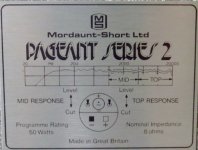
I was hoping for information & assistance with a pair of Mordaunt Short Pageant Series 2 Loudspeakers.
The owner finds that they no longer sparkle for her.
I played a familiar track on them and found they're a little dull sounding and lack sharpness across the range.
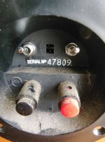
The 2 toggle switches on the rear are a little strange.
Both are set in the up position, but will not switch downwards.
I've put some force on them but they won't budge.
I was concerned not to put too much more force on them for fear of damage.
1. Are the toggles switchable up & down and which direction is flat & which is bright?
2. Do these toggles switch the path between direct & through the resistors?
3. Is it desirable to avoid the signal going through resistors, especially cheap ones?
4. If I leave them switched bypassing the resistors, then is it pointless replacing the resistors?
5. Is it worth replacing the electrolytic caps to poly or should I just get fresh reasonable electrolytic replacements?
I plan to remove and measure current caps, but thought I'd post first.
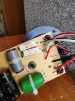
There is currently a single 10mfd & 2 x 5mfd's fitted to the x over.
thanks cliff
Sorry for my absence from the forum.
Had been caring for my mother, who recently passed away.
I was hoping for information & assistance with a pair of Mordaunt Short Pageant Series 2 Loudspeakers.
The owner finds that they no longer sparkle for her.
I played a familiar track on them and found they're a little dull sounding and lack sharpness across the range.
The 2 toggle switches on the rear are a little strange.
Both are set in the up position, but will not switch downwards.
I've put some force on them but they won't budge.
I was concerned not to put too much more force on them for fear of damage.
1. Are the toggles switchable up & down and which direction is flat & which is bright?
2. Do these toggles switch the path between direct & through the resistors?
3. Is it desirable to avoid the signal going through resistors, especially cheap ones?
4. If I leave them switched bypassing the resistors, then is it pointless replacing the resistors?
5. Is it worth replacing the electrolytic caps to poly or should I just get fresh reasonable electrolytic replacements?
I plan to remove and measure current caps, but thought I'd post first.
There is currently a single 10mfd & 2 x 5mfd's fitted to the x over.
thanks cliff
Attachments
Hi
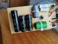
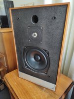
Just some shots of the speakers themselves.
At least one of them.
Interestingly the serial number on each of them is the same.
My sisters JBL's from the 70's have consecutive numbers.
It seems some manufacturers allocated individual serial numbers for each Loudspeaker, where as others allocated the same number for each of a pair.
Attachments


Thanks Allen.
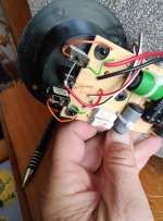
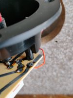
The toggles on these switches are smaller than the usual toggle I'm familiar with.
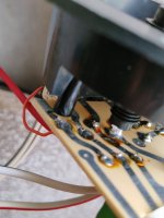
Each switch has three wire points on the rear to which wiring can be connected.
Do you think non MS parts are available?
Or should I try to by pass the two switches altogether and, if the resistors are currently engaged on the -ve pole of the switch positions, bypass the resistors altogether?
The toggles on these switches are smaller than the usual toggle I'm familiar with.
Each switch has three wire points on the rear to which wiring can be connected.
Do you think non MS parts are available?
Or should I try to by pass the two switches altogether and, if the resistors are currently engaged on the -ve pole of the switch positions, bypass the resistors altogether?
Sorry to hear about your mother, Cliff, but welcome back to the forum.
I would certainly replace those ELCAP capacitors with modern bipolar electrolytics. They are probably well out of spec by now.
Replace the 5 uF with 4.7 uF.
When the switches are in the down or 'cut' position, resistors are introduced to attenuate the mid and treble drivers.
Currently they are in the up or "level" position and it sounds like Allen B is correct.
It would be best if you were to bypass the switches and their associated resistors and run the mid and tweeter direct from the crossover board.
This vintage speaker requires as much 'brightness' as you can muster!
EDITED!!
Last edited:
Thanks Galu.
It's good to reconnect. 🙂
Do you know a good source of electrolytics worth using, in Oz?
I looked at film caps (Jantzen Standard & CrossCap), but do you think this is overkill for the likely result?
I'll need to get my head around the wiring in order to by pass the switches/resistors.
It's good to reconnect. 🙂
Do you know a good source of electrolytics worth using, in Oz?
I looked at film caps (Jantzen Standard & CrossCap), but do you think this is overkill for the likely result?
I'll need to get my head around the wiring in order to by pass the switches/resistors.
I'd consider disconnecting the switches and making a choice with the wiring. Can you draw a schematic or at least show clear photos of each side of the board, + indicate where the wires go..
Do you know a good source of electrolytics worth using, in Oz?
I looked at film caps (Jantzen Standard & CrossCap), but do you think this is overkill for the likely result?
I can't comment on suppliers in Oz, but any good brand of bipolar electrolytic capacitor will do, such as the Mundorf Ecap.
Expensive film caps would be overkill in my opinion, but you could try standard quality polypropylene capacitors if you want to experiment on tweaking the sound.
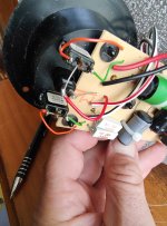
Re bypassing/disconnecting the switches and resistors, as AllenB says, we need to know where each one of the coloured wires on the right of the crossover board goes.
Jaycar sell them for 55cDo you know a good source of electrolytics worth using, in Oz?
Hi.
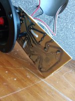
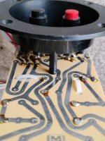
Here are shots of the circuit board, switches & wiring.
I'll next try to follow the wiring.
The jaycar electrolytics are +-10%, perhaps a little too cheap & cheerful for the speakers.
Trying to locate an Oz source for the Mundorp E Caps which stocks the range.
Here are shots of the circuit board, switches & wiring.
I'll next try to follow the wiring.
The jaycar electrolytics are +-10%, perhaps a little too cheap & cheerful for the speakers.
Trying to locate an Oz source for the Mundorp E Caps which stocks the range.
Attachments
It looks like it would be much easier to simply replace the switches.
Look for a 3 pin on-on SPDT toggle switch that would fit the existing mounting holes.

Look for a 3 pin on-on SPDT toggle switch that would fit the existing mounting holes.
The tolerance is not necessarily a factor to judge by with electrolytics.The jaycar electrolytics are +-10%, perhaps a little too cheap & cheerful for the speakers.
However, M-LYTIC audio grade power caps are not like the ones used in loudspeaker crossovers.
They are power capacitors used in amplifiers where the tolerance can be larger. They come in values from 1,000 uF to 47,000 uF.

https://www.mundorf.com/audio/en/shop/Capacitors/Power_Caps/MLytic_AG/
They are power capacitors used in amplifiers where the tolerance can be larger. They come in values from 1,000 uF to 47,000 uF.
https://www.mundorf.com/audio/en/shop/Capacitors/Power_Caps/MLytic_AG/
Last edited:
You don't think the point remains?
Cliff, it's difficult to see the whole board as well as where the wires go.
Cliff, it's difficult to see the whole board as well as where the wires go.
You don't think the point remains?
I think that +/-10% is adequate for a simple crossover network like the one in question.
The original black and red ELCAP capacitors are unlikely to have been of closer tolerance than that.
Cliff, the simplest way forward is to replace the switches as I've indicated. Personally, I've no desire to make myself dizzy by trying to unravel the wiring!
I don't see the logic in a statement like this. You can narrow down tolerance simply by measuring them and selecting one that has near the exact value. We could also get into the variability of electrolytics over time, but again tolerance is not necessarily the spec to tell you that.I think that +/-10% is adequate for a simple crossover network
You can narrow down tolerance simply by measuring them and selecting one that has near the exact value.
I'm well aware of that and have frequently done so.
P.S. Make that +/-5%. 😀
Last edited:
Thanks Galu.It looks like it would be much easier to simply replace the switches.
Look for a 3 pin on-on SPDT toggle switch that would fit the existing mounting holes.
View attachment 1275862
I'll work on tracking down some replacement switches.
Hi Allen.electrolytics
Do you have any Oz sources for Mundorp ECaps?
cheers Cliff
- Home
- Loudspeakers
- Multi-Way
- Assistance with Mordaunt Short Pageant Series 2