Hey guys, usually I post amps in here on this forum however, I thought you will like also some unique speakers 😉
I am building speakers similar to B&W 800D, but its not copy nor clone. Its build from scratch by me using non bw speakers. Ofc I saw youtube videos of build process as well as diy copies. I am not doing that, I go my way but I like the design and some features so I am going to use it as a template.
This is going to be build thread of some sort, even though I am in the middle of process, but anyways... I was posting processes I did so far on the local cz forum, but I think this deserves wider presentation 🙂
Begining...
To make this all possible I started with mid speaker as they call it "turbine head". I told to myself that if I am not going to have this midrange speaker enclosure, its pointles to do anything or start by other parts... so I started to draw in Blender, a lot. It looks simple, but modeling really nice teardrop isnt as simple as it looks on first sight. Original b&w is very prolonged and I didn't wanted my speakers to be as big and deep. So I shortened it and modeled for standard speaker size. The result is 42cm deep teardrop with nearly 30cm diameter. First concept below:

I have a friend who is master of 3d printing so he did print these for me out of PLA. Wall is about 7mm thick with trippled outside walls. I didnt wanted exotic materials, because of several reasons: price, and mainly print realiability. This was printed for nearly 2 days a piece. To make very shallow angles printable its impossible to make it as a one print so my teardrops are glued from two parts by epoxy. To make precise fit I printed also small guides and also speaker mount is sandwitched thanks to that. Below a few pictures of wall "cut" from one damaged print and front piece + tear piece prepared for glue:


more glue:

glued it already looked amazing, it had very nice "pearl" shine thanks to print layers, however because of front piece it looked not as good so I had to do something about it. I watched milion videos how to smooth 3d prints but tried my own way as the main point was somehow same. So I sanded all surface by 80grit, then I filled all surface by 2part polyester filler specifically for plastics. A lot of sanding and dirt... i looked like narco baron 🤣


the result was really smooth, but not enough so one more layer and after sanding:

all 3d print raster dissapeared and I was prepared for primer. First coat was like indicator where the bad spots still are so again sanding and more primer coats. After about 4th or 5th coat of primer and water sanding it was absolutely smooth. I was very happy with the result so I knew the main part is acomplished so I started ordering wood and remaining parts. (I'll get back to teardrop later no worries)
Main body
After I modeled whole speaker body in blender I started to export particular parts into autocad to prepare shapes to be cnc cut from mdf. I wanted all internal matrix parts to be cnced because of consistency which would be impossible to be done by hand. Honestly, it was extremely difficult to find company for this small task, I was searching for a month and some not even responded to my emails, some after second mail stopped communication 🙁 terrible. After long search I found some young guys doing something compeltely different than wood but they had cnc and helped me, maybe a luck but finaly I got my parts:

only the matrix parts are CNCed, I did front baffle by myself with mill as well as some other pieces to safe time and money. One particular tricky piece was doing big radiuses on top and bottom edge of the front baffle. So I did some calculations and milled steps to get the rough radius, looked like this:


so i could smooth out and respect the radius I have made radius sanding tool out of cut piece of PVC pipe:
the result using this custom tool:
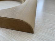
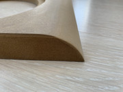
bottom radius is smaller ~30mm as there is wall continuing by 10° angle and top bigger radius is ~40mm to smoothly continue on 25° top wall.
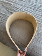
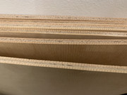
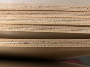
After I had all the pieces I needed to figure out what to use for curved walls. I've found out, there is a thing called flexible ceiba plywood so i have order a few sheets 8mm thick and let them cut to size. I was a bit worried by how flexible it is but oh my... it is wobbly and bendy!
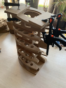
some matrix putting together:
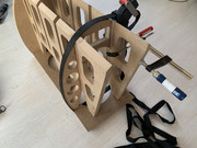
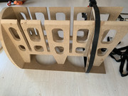


To make box "standing" at least on a piece of flat part I did small ending at the back flat where the screw holder will go:


more sanding and connecting radiuses:


I am building speakers similar to B&W 800D, but its not copy nor clone. Its build from scratch by me using non bw speakers. Ofc I saw youtube videos of build process as well as diy copies. I am not doing that, I go my way but I like the design and some features so I am going to use it as a template.
This is going to be build thread of some sort, even though I am in the middle of process, but anyways... I was posting processes I did so far on the local cz forum, but I think this deserves wider presentation 🙂
Begining...
To make this all possible I started with mid speaker as they call it "turbine head". I told to myself that if I am not going to have this midrange speaker enclosure, its pointles to do anything or start by other parts... so I started to draw in Blender, a lot. It looks simple, but modeling really nice teardrop isnt as simple as it looks on first sight. Original b&w is very prolonged and I didn't wanted my speakers to be as big and deep. So I shortened it and modeled for standard speaker size. The result is 42cm deep teardrop with nearly 30cm diameter. First concept below:
I have a friend who is master of 3d printing so he did print these for me out of PLA. Wall is about 7mm thick with trippled outside walls. I didnt wanted exotic materials, because of several reasons: price, and mainly print realiability. This was printed for nearly 2 days a piece. To make very shallow angles printable its impossible to make it as a one print so my teardrops are glued from two parts by epoxy. To make precise fit I printed also small guides and also speaker mount is sandwitched thanks to that. Below a few pictures of wall "cut" from one damaged print and front piece + tear piece prepared for glue:
more glue:
glued it already looked amazing, it had very nice "pearl" shine thanks to print layers, however because of front piece it looked not as good so I had to do something about it. I watched milion videos how to smooth 3d prints but tried my own way as the main point was somehow same. So I sanded all surface by 80grit, then I filled all surface by 2part polyester filler specifically for plastics. A lot of sanding and dirt... i looked like narco baron 🤣
the result was really smooth, but not enough so one more layer and after sanding:
all 3d print raster dissapeared and I was prepared for primer. First coat was like indicator where the bad spots still are so again sanding and more primer coats. After about 4th or 5th coat of primer and water sanding it was absolutely smooth. I was very happy with the result so I knew the main part is acomplished so I started ordering wood and remaining parts. (I'll get back to teardrop later no worries)
Main body
After I modeled whole speaker body in blender I started to export particular parts into autocad to prepare shapes to be cnc cut from mdf. I wanted all internal matrix parts to be cnced because of consistency which would be impossible to be done by hand. Honestly, it was extremely difficult to find company for this small task, I was searching for a month and some not even responded to my emails, some after second mail stopped communication 🙁 terrible. After long search I found some young guys doing something compeltely different than wood but they had cnc and helped me, maybe a luck but finaly I got my parts:
only the matrix parts are CNCed, I did front baffle by myself with mill as well as some other pieces to safe time and money. One particular tricky piece was doing big radiuses on top and bottom edge of the front baffle. So I did some calculations and milled steps to get the rough radius, looked like this:
so i could smooth out and respect the radius I have made radius sanding tool out of cut piece of PVC pipe:
the result using this custom tool:
bottom radius is smaller ~30mm as there is wall continuing by 10° angle and top bigger radius is ~40mm to smoothly continue on 25° top wall.
After I had all the pieces I needed to figure out what to use for curved walls. I've found out, there is a thing called flexible ceiba plywood so i have order a few sheets 8mm thick and let them cut to size. I was a bit worried by how flexible it is but oh my... it is wobbly and bendy!
some matrix putting together:
To make box "standing" at least on a piece of flat part I did small ending at the back flat where the screw holder will go:
more sanding and connecting radiuses:
Last edited:

Back to 3D printing...
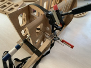
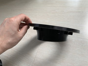
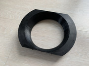
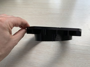
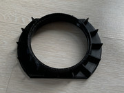
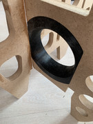
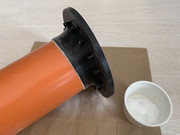
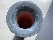
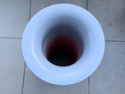
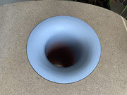
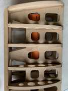
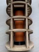
searching for original bw bass port was not successful or it was unreasonably expensive for such a small piece of plastic, looking for what was available online I found some but there were some compromises and didnt wanted that also very expensive solutions. So I modeled my own, BIG and hell of a curved bassreflex ports. Again, to make shallow angles printable its made out of two pieces glued together:
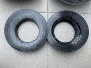
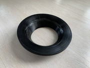
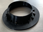
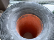
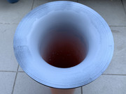
The outer port is nearly 20cm outside diameter optimized for classic 110mm PVC pipe. I did one very nice feature I am very proud of. I didnt like the port tube being angled as the bass port is going to be on bottom wall which is angled by 10° by doing this me port is quite long and would end up somewhere at rear wall what I didn liked. So I designed funnel shape under 5° angle. Also the second inner piece is precisely shaped to fit within one of the inner matrix cutout and is also angled by 5°. So as those two coutns it makes ideal 10° bass port which is very sturdy placed inside of cabinet:
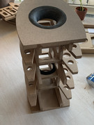
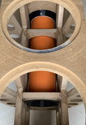
The get the idea how the port is goign to be placed:
glueing port by CA glue + baking soda:
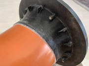
more sanding, filling, painting:
I am writing this while waiting for the glue to cure and this too much writing at once for me so more to come soon..
searching for original bw bass port was not successful or it was unreasonably expensive for such a small piece of plastic, looking for what was available online I found some but there were some compromises and didnt wanted that also very expensive solutions. So I modeled my own, BIG and hell of a curved bassreflex ports. Again, to make shallow angles printable its made out of two pieces glued together:
The outer port is nearly 20cm outside diameter optimized for classic 110mm PVC pipe. I did one very nice feature I am very proud of. I didnt like the port tube being angled as the bass port is going to be on bottom wall which is angled by 10° by doing this me port is quite long and would end up somewhere at rear wall what I didn liked. So I designed funnel shape under 5° angle. Also the second inner piece is precisely shaped to fit within one of the inner matrix cutout and is also angled by 5°. So as those two coutns it makes ideal 10° bass port which is very sturdy placed inside of cabinet:
The get the idea how the port is goign to be placed:
glueing port by CA glue + baking soda:
more sanding, filling, painting:
I am writing this while waiting for the glue to cure and this too much writing at once for me so more to come soon..
Are all of those externally hosted images going to survive long term?
Discussion here:
https://www.diyaudio.com/community/threads/externally-hosted-images.380271/
Discussion here:
https://www.diyaudio.com/community/threads/externally-hosted-images.380271/
This is a sizeable effort and a treat to watch.
Apart from your outstanding building skills, this is the most powerful sentence in the whole write up.I am not doing that, I go my way
Amazing, thanks for sharing.
Hugo
mattstat interesting, will try later to modify, but I am not making museum here, I am just posting recent process... should've go to instagram or blog site  edit: I can attach only 20 files so other pictures will stay externally hosted.
AllenB thank you
Netlist thank you 🙂 yes there are more reasons, mainly price of original drivers and overall size. I wanted something that looks like 800d but uses smaller drivers like 802d but overal is not as big...
btw I found out I am able to edit only my first post so going to continue with description by new posts below
edit: I can attach only 20 files so other pictures will stay externally hosted.AllenB thank you
Netlist thank you 🙂 yes there are more reasons, mainly price of original drivers and overall size. I wanted something that looks like 800d but uses smaller drivers like 802d but overal is not as big...
btw I found out I am able to edit only my first post so going to continue with description by new posts below
Last edited:
I didn't know original drivers were available. I thought B&W was working with a trade-in system for them.
Hugo
Hugo
More cabinet building... teardrop seat was the most difficult part to make, I felt like sculpture artist 😀 the problem is its curved and also gradually increasing cut angle - insane  I did print template and somehow did it by hand but I think I should have make this piece by cnc also 🙁 a lot of sanding was required...


more glueing... as it didn't fit the front baffle very precisely and there was slight mismatch with angles (±1 degree) I used epoxy to glue this top piece


side view + trying feets


Sanding of connecion to make it super smooth:


Transition was not very straight as I would like to, you cannot see that from images maybe but there were slight dents after sand proces so I used poly filler to fix the issue:

Cabinets were somehow prepared for the back walls. However to have perfect fit I leveled all the "fins" of matrix with big sanding tool I made = glued 60grit to 1m long wooden desk and sanded surrounding:

thats it about the box for now. Today I am glueing back walls so some pics of that soon. However before that I will write more about teardrop finish when will have time, maybe this evening.
I did print template and somehow did it by hand but I think I should have make this piece by cnc also 🙁 a lot of sanding was required...more glueing... as it didn't fit the front baffle very precisely and there was slight mismatch with angles (±1 degree) I used epoxy to glue this top piece
side view + trying feets
Sanding of connecion to make it super smooth:
Transition was not very straight as I would like to, you cannot see that from images maybe but there were slight dents after sand proces so I used poly filler to fix the issue:
Cabinets were somehow prepared for the back walls. However to have perfect fit I leveled all the "fins" of matrix with big sanding tool I made = glued 60grit to 1m long wooden desk and sanded surrounding:
thats it about the box for now. Today I am glueing back walls so some pics of that soon. However before that I will write more about teardrop finish when will have time, maybe this evening.
Nice.I felt like sculpture artist 😀 the problem is its curved and also gradually increasing cut angle - insane
Continuing with the teardrop finish... so I ended with very smooth primer surface after about 5 coats sanded under water by 320grit. it was very very smooth 🙂 well still some details here and there I will not lie, but overall looked very nice if I realise where I started 😀


I used normal acrylic car spray, nothing fancy. They said to me at shop its impossible to polish it as it does not contain hardener... but well its summer and sun = hardener like hell with black paint 😀 and based on my previous experience I gave it a try. A first coat:
yes its simple as that 🙂 after first two coats it was very nice, shiny but shine had orange distortion as usual with this process:


so I sanded it whole once again with 2000 grit and applied third coat, I thought its finished so tried some polishing. It went really well and mirror gloss was present, however very distant reflection was still muddy. I was somehow satisfied with the result:

however an accident happened and teardrops fell on ground when they were resting. I was very disappointed to start it all over again and wanted to do some local repair, however it was visible where repainted. So I took a few steps back and smoothed out all over again with 1000 grit. This step back helped very much btw! I applied next thick coat, it was total 4th and that was the best and final one. So yes, good finish require many coats indeed.
I did more polishing starting with 2000/3000 grit paper under water, after that medium paste, continued by fine polishing paste and finished it with carnauba wax. The result looks like this:


next.... concrete plinth
I used normal acrylic car spray, nothing fancy. They said to me at shop its impossible to polish it as it does not contain hardener... but well its summer and sun = hardener like hell with black paint 😀 and based on my previous experience I gave it a try. A first coat:
yes its simple as that 🙂 after first two coats it was very nice, shiny but shine had orange distortion as usual with this process:
so I sanded it whole once again with 2000 grit and applied third coat, I thought its finished so tried some polishing. It went really well and mirror gloss was present, however very distant reflection was still muddy. I was somehow satisfied with the result:
however an accident happened and teardrops fell on ground when they were resting. I was very disappointed to start it all over again and wanted to do some local repair, however it was visible where repainted. So I took a few steps back and smoothed out all over again with 1000 grit. This step back helped very much btw! I applied next thick coat, it was total 4th and that was the best and final one. So yes, good finish require many coats indeed.
I did more polishing starting with 2000/3000 grit paper under water, after that medium paste, continued by fine polishing paste and finished it with carnauba wax. The result looks like this:
next.... concrete plinth
Last edited:
Wow wow wow 🤩. What a beautiful display of patience, and talent and hard working dedication to this project. I hope they blow your expectations out of the water. I can’t wait to see the finial product finished. Crossovers are going to be massive (if I had to guess? Unless your going active on all the drivers and they have their own amplifiers and crossovers points). We’ll take it easy and be safe. Nice Job. Jeff
Man oh man that’s beautiful work. You are a real craftsman.
good question, combination of mid to low-end is probably the right answer 😀 but seriously I don't want to invest too much into expensive drivers I will not benefit from. I simply do not hear difference between 100 and 1000e speakers and I do not listen on big ones very often. I do the build because the process is fun and what entertains me, not the final product, thats just cherry on top 🙂Which transducers will you be using for your project ?
For lows I am going to use 2x SB23MFCL45 (goes nice and low in small volume)
For mids HiVi L6 (looks like no serious resonances thanks to kevlar and quite nice dispersion, will see more after measurements)
For highs not sure yet, I was planning HiVi TN28 mainly because ready to use housing, but I realise the low quality of that tweeter. I have it in other boxes and sound-wise I am satisfied. But I was thinking of printing some universal holder to accommodate also usual standard dome tweeters. I was thinking about what one friend adviced - Bliesma beryllium but I am still not sure. I tihnk I will try what I have and will see... I dont like that big housing on top of teardrop, does not look nice 😀
Below some driver pics. As HiVi L6 has awful rim I printed small trim piece around


Jeffrey01 yes crossovers will be probably big. I plan to place them inside the cavity at the bottom of plinth, space I prepared is 1sq feet and 2 inches high, I hope that will be enough 🤣
Till now I was describing mostly what i was doing for last 6 months but getting to point where I am at current processes and plinths are curing atm. Pics and description in a few days...
Regardless of what drivers you use, these beautiful cabinets deserve equal patience, care and a willingness to learn and grow when doing measurements and crossover design work.
It seems like you have that in spades.
Lots of help available here if needed. Yours truly and @vineethkumar01 @hifijim @fluid
It seems like you have that in spades.
Lots of help available here if needed. Yours truly and @vineethkumar01 @hifijim @fluid
Last edited:
I've released plinths from the forms today, they still have to cure, but anyway more about those...
I have not yet decided what finish I'll do on cabinets but no matter the black color or lacquered wood I want industrial look of the speakers. To both of these fits the best just pure natural concrete. I have used this in my previous projects and very liked it, so it was decided. My first idea was to do just thin plinths and put crossover inside the cabinets. Due to many, mostly practical, reasons I've decided to make plinths thick and make cavity from the bottom to accommodate the crossovers.
Each plinth is approx 37x48cm and 7cm high. Walls are ~4cm thick, front to carry most of the weight is 10cm and top wall is just ~2cm. To precisely copy curve of the cabinets, the forms are cut by CNC. I made form walls from standard laminated wood + leftovers from cutting plywood. As a separator, and also to make plywood surface smooth I used cheap self-adhesive foil on all the walls. To make transition in corners soft I filled them with silicone, this helped to make it also water-tight:


As you can see I pre-formed also all the holes needed for fastening it to the cabinet as well as the speaker terminals. My first idea how to make fancy cavity was use of plastic food containers. However I struggled quite a lot how to connect it to next parts and following cavities such as the one for binding post and back screw part. Finally to form hollow inside I used classic polystyrene 2+3cm panels in between which I put screws on strategic places to be able to fasten nuts into the concrete to make holders for PCBs of crossovers:


To make parallel cavity for binding posts I did special cutouts and also "raised" part within cavity so screw holding cabinet has more rigidity and there is still channel to carry wires around:

As you can see in previous pictures I wanted to put some mesh into concrete to make it stronger, especially in that "thin" 2cm top wall part. I used some old metal mesh shelfs I wanted to throw away but they found its proper use! 😀 So they could levitate and make it "flow" I used just a piece of wire and some hot glue to secure it on proper spot:

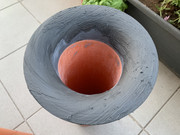
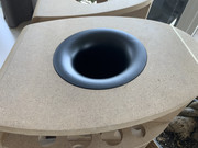
Everything was prepared for concrete pour. I have used fast, fine and strong concrete, what appeared to be a mistake and it was in fact VERY fast curing one, in 10-15 minutes its becoming to be solid so you cannot fix the mistakes 🙁 I had no chance to even vibrate the thing so for next one I used more water to make it flow better. Anyway everything was successful, I also put in pvc pipe end pieces to create a small seats for metal roller feets:


After a day, to get water into center of concrete to give it better chance to cure properly I removed polystyrene and filled it with water. I was curing it like that for 3 days watering it 5times a day:

Today morning I removed all forms and drilled out all the wood channels, forms are ready and very nice and smooth! There were only minor defects, a small bubble here or there which I simply filled with fine cement+sand mixture. I will keep watering it for at least a week to cure stronger... after that I will put clear water-based varnish on it.


Surprisingly its not that heavy as I expected it to be, just ~14kg a piece
I have not yet decided what finish I'll do on cabinets but no matter the black color or lacquered wood I want industrial look of the speakers. To both of these fits the best just pure natural concrete. I have used this in my previous projects and very liked it, so it was decided. My first idea was to do just thin plinths and put crossover inside the cabinets. Due to many, mostly practical, reasons I've decided to make plinths thick and make cavity from the bottom to accommodate the crossovers.
Each plinth is approx 37x48cm and 7cm high. Walls are ~4cm thick, front to carry most of the weight is 10cm and top wall is just ~2cm. To precisely copy curve of the cabinets, the forms are cut by CNC. I made form walls from standard laminated wood + leftovers from cutting plywood. As a separator, and also to make plywood surface smooth I used cheap self-adhesive foil on all the walls. To make transition in corners soft I filled them with silicone, this helped to make it also water-tight:
As you can see I pre-formed also all the holes needed for fastening it to the cabinet as well as the speaker terminals. My first idea how to make fancy cavity was use of plastic food containers. However I struggled quite a lot how to connect it to next parts and following cavities such as the one for binding post and back screw part. Finally to form hollow inside I used classic polystyrene 2+3cm panels in between which I put screws on strategic places to be able to fasten nuts into the concrete to make holders for PCBs of crossovers:
To make parallel cavity for binding posts I did special cutouts and also "raised" part within cavity so screw holding cabinet has more rigidity and there is still channel to carry wires around:
As you can see in previous pictures I wanted to put some mesh into concrete to make it stronger, especially in that "thin" 2cm top wall part. I used some old metal mesh shelfs I wanted to throw away but they found its proper use! 😀 So they could levitate and make it "flow" I used just a piece of wire and some hot glue to secure it on proper spot:
Everything was prepared for concrete pour. I have used fast, fine and strong concrete, what appeared to be a mistake and it was in fact VERY fast curing one, in 10-15 minutes its becoming to be solid so you cannot fix the mistakes 🙁 I had no chance to even vibrate the thing so for next one I used more water to make it flow better. Anyway everything was successful, I also put in pvc pipe end pieces to create a small seats for metal roller feets:
After a day, to get water into center of concrete to give it better chance to cure properly I removed polystyrene and filled it with water. I was curing it like that for 3 days watering it 5times a day:
Today morning I removed all forms and drilled out all the wood channels, forms are ready and very nice and smooth! There were only minor defects, a small bubble here or there which I simply filled with fine cement+sand mixture. I will keep watering it for at least a week to cure stronger... after that I will put clear water-based varnish on it.
Surprisingly its not that heavy as I expected it to be, just ~14kg a piece
You’re a jack of all trades😁👍. Wow am learning so much from this post. 😁. Yes working with cement is not easy but, I have worked with quick Crete and other brands not so much and can tell when it’s ready use. I can tell by looking at the mixture and what it’s consistency should look like and feel. Learned by plugging the old metal rods they put through the old basement walls to hold them together. Corking the holes and cementing them have been a easy task now for me. Thanks for sharing. Awesome a job😁.
- Home
- Loudspeakers
- Multi-Way
- 802 Diy speakers