I was offered a Sae A205 amp, there is not much info out there, plenty of power, looks like a Acurus or Adcom mosfet amp.
but I am not sure.
Is this a Mosfet amp ?
what are the bias number without a service manual ?
Is the design any good ?
100wpc Class A/200wpc Class AB1.
4x Toshiba 2SA1302, 4 x 2SC3281 each side
thanks for your help

but I am not sure.
Is this a Mosfet amp ?
what are the bias number without a service manual ?
Is the design any good ?
100wpc Class A/200wpc Class AB1.
4x Toshiba 2SA1302, 4 x 2SC3281 each side
thanks for your help
Attachments

Definitely very powerful classAB amp, but never 100 watts in classA. Thats nonsense. Maybe a watt or two.
From my SAE experience in the old days, i would look at it as a parts supply for a better sounding amplifier.
dave
dave
I did some research about the amp, according to guy from audiokarma, here are pseudo service manual by Motorola
http://www.cieri.net/Documenti/Altr...eband-Low Feedback Design (AN1308 - 1992).pdf
see fig 26 and and 35
I not very tech savvy, what is the roll of Motorola on the design of the amp ?
http://www.cieri.net/Documenti/Altr...eband-Low Feedback Design (AN1308 - 1992).pdf
see fig 26 and and 35
I not very tech savvy, what is the roll of Motorola on the design of the amp ?
You need to read the whole article. It's actually very good.
They designed two amplifiers around their (famous) BJTs...

They designed two amplifiers around their (famous) BJTs...
Did he designed the A205 with the same philosophy ?
are fig 26 and 35 the schematic pretty much ?
Not much info out there
What do you make of the design ?
are fig 26 and 35 the schematic pretty much ?
Not much info out there
What do you make of the design ?
where did you get that from?Is a very simplistic amp with a lot of power
Yet another "leach" amp ( fully complimentary).
Strengths =
- Very good PSRR , they cancel supply ripple natively.
-simple and easy to understand with simple compensation - very stable.
Weaknesses = 3rd and 5th distortion products and will always require offset adjust
and-or P/N matching.
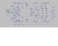
Below is the simple version of this topology , used in most A/B subwoofer plate amps (80% of them). Still .01% THD.
Dayton plate amps are this circuit.
Strengths =
- Very good PSRR , they cancel supply ripple natively.
-simple and easy to understand with simple compensation - very stable.
Weaknesses = 3rd and 5th distortion products and will always require offset adjust
and-or P/N matching.
Below is the simple version of this topology , used in most A/B subwoofer plate amps (80% of them). Still .01% THD.
Dayton plate amps are this circuit.
Attachments
thanks for the review of the amp, got it for $75 plus shipping
How do you adjust the bias ?
There is a switch is the back for 100 watts and 200 watts, what is the difference ?
Some pic of the amp
http://i462.photobucket.com/albums/qq350/62sunbeam/67b7a04c.jpg
http://i462.photobucket.com/albums/qq350/62sunbeam/4e5162ae.jpg
http://i462.photobucket.com/albums/qq350/62sunbeam/f342b23d.jpg
http://i462.photobucket.com/albums/qq350/62sunbeam/de983236.jpg
http://i462.photobucket.com/albums/qq350/62sunbeam/6fe2405a.jpg
Good deal , the case and the amp for 75$ ... I'd buy it. Trafo alone goes for 100$+
Bias , first test one of the emitter resistors (big grey ones). 20mV would give you @40mA per device.
I don't see any trimmers for either offset or bias on any google picture of this amp.
What were they thinking ??
Board layout looks different from either schematic.
Zener biased LTP's , no ripple eaters , no adjustment trimmers offset by top quality silver mica caps and a beefy
power supply ???? strange.
OS
- Home
- Amplifiers
- Solid State
- SAE A205 amp, mosFET?