Hi all, I'm at a stalemate with an American Bass VFL 20k Competition series. I replaced several damaged components including 20N50F output mosfet, TC4452 gate driver, IR2184 Half Bridge driver but still the amp won't work.
I believe that the problem revolves around the IR2184 driver and its reference power supplies on pins 5 and 8. In fact, during the start-up phase, the 12v referred to the negative rail is fixed on pin 5; while on pin 8 the 12v referred to gnd are missing after a few seconds. In this condition pin 4 (low side output) seems to work properly while pin 7 (High Side output) does not work. This situation puts the amp in protection mode and the power supply switches off. I checked everything, but something still escapes me .... do you have any suggestions???? Thank you for what you are going to do, greetings.
Andrea.
On the input side of the output filter inductor, do you ever see rail-rail oscillation as the amp tries to power up?
On the output side of the output filter inductor (during that same time), do you see a large pulse of DC Voltage?
Are all of the components in the amp at this time?
Is the initial mute delay (on the SD pin) working normally?
On the output side of the output filter inductor (during that same time), do you see a large pulse of DC Voltage?
Are all of the components in the amp at this time?
Is the initial mute delay (on the SD pin) working normally?
Hi Perry, thanks for your response and for giving me the opportunity to engage with other forum members. At the moment I have disassembled all the mosfets from the amplifier, I can confirm you that before the output inductor I don't see any oscillation and while the amplifier tries to turn on I see a big DC voltage pulse. The initial squelch delay (on the SD pin) works normally. Without Mosfet the IR2184 driver oscillates only on pin 4 (Lo Out)
Last edited:
You won't typically get high-side oscillation (no output FETs installed) unless you supply voltage for the high side. I typically use a 9v battery.
Hi, How many hz signals do you see at the output on the low side gate if the output mosfets are not installed?
@Pa.Subwoofer: Hi, I don't remember the exact oscillation frequency now... as soon as I get back to the lab I can check it.
@Parry Babin: Hi Perry I agree with you, If I apply an external voltage (typ.12v) on the VCC pin of the TC4452, the driver also starts to oscillate on pin 7. You asked me too if I could see a big jump in DC voltage when turning on the amp. I confirm that this is exactly what happens and immediately after, the amp goes into protection mode by turning off the SMPS.
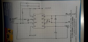
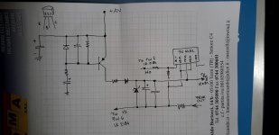
I attach some rather primitive drawings of the wiring diagram. I hope they are accurate. There are no references to individual components but they can be useful for understanding something more.
@Parry Babin: Hi Perry I agree with you, If I apply an external voltage (typ.12v) on the VCC pin of the TC4452, the driver also starts to oscillate on pin 7. You asked me too if I could see a big jump in DC voltage when turning on the amp. I confirm that this is exactly what happens and immediately after, the amp goes into protection mode by turning off the SMPS.
I attach some rather primitive drawings of the wiring diagram. I hope they are accurate. There are no references to individual components but they can be useful for understanding something more.
Attachments

without mosfet output I have no pulse in DC. With the mosfets mounted I have a DC pulse of about 90Volt on the output inductor which sends the amp into protection. I'm thinking of some offset problem
@gioan_77
Can you show a high quality picture of the driver board? Did you change anything on it?
Did you replace all 4 tc4452?
Carefully start the amplifier because there is a chance that the low and high side will short circuit if the amplifier does not start properly (with mosfets, of course) 🙂
Can you show a high quality picture of the driver board? Did you change anything on it?
Did you replace all 4 tc4452?
Carefully start the amplifier because there is a chance that the low and high side will short circuit if the amplifier does not start properly (with mosfets, of course) 🙂
😀 yes I can..... on the driver board I changed only the Half Bridge Driver IR2184, because the comparator chip and the operational chip work properly. I changed all 4 TC.
i just finished repairing a vfl 22k. im assuming the circuits are similar. does urs have 1 or 2 driver cards with an irs2184s?
check the j111 transistor next to the driver card. also check the little green inductor next to the 12v regulator
Hi all, the amp has just 1 driver card.
the j111 on the driver card if I'm not mistaken acts as a muting on the audio signal of the opamp...small green inductor already replaced 😕
the j111 on the driver card if I'm not mistaken acts as a muting on the audio signal of the opamp...small green inductor already replaced 😕
The j111 drives the shutdown pin of the 2184. It has to clamp the SD voltage for a brief time during the initial mute delay as well as when the amp is shut down. In some instances, if this circuit isn't working properly, it can cause the output FETs to fail during startup or shutdown.
Does the amp go into protect without the output FETs in the circuit?
Does the amp go into protect without the output FETs in the circuit?
When driving a signal into the amp (so you will have drive pulses on the driver IC), does the rail voltage develop fully before the drive pulses start? See video for an example.
https://www.bcae1.com/temp/ampstartup01.mkv
https://www.bcae1.com/temp/ampstartup01.mkv
there are 2 j111s... one on the motherboard that takes care of the ir2184 SD, the other is an SMT mounted on the driver board and mutes the TL072.... and they both work.....
Perry, now you're taking me by surprise, I don't remember... I'm not in the lab and I have to verify what you asked me... over the weekend I'll get back to work with it and I'll tell you exactly.
You stated that you have two J111s. Are you sure that the one on the driver board is a J111?
My notes (which may be in error, of from a different revision) have a J113 on the driver board.
My notes (which may be in error, of from a different revision) have a J113 on the driver board.
- Home
- General Interest
- Car Audio
- AmericanBass VFL competition 20k in protect mode