Hello
I'm new to this forum and I would like to hear your thoughts on my chip amp design.
The idea is that I can use this as a normal amp and a guitar amp.
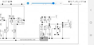
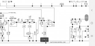
In the preamp/buffer section there are two NE5532 opamps, one with no gain and one with gain in parallel. The power section has a TDA7267 opamp.
In normal amp mode the drive mix knob is all the way down, that means no overdrive is mixed in the signal. If overdrive is needed the drive mix knob can blend in some overdrive.
What do you think?
Any help is appreciated!

I'm new to this forum and I would like to hear your thoughts on my chip amp design.
The idea is that I can use this as a normal amp and a guitar amp.
In the preamp/buffer section there are two NE5532 opamps, one with no gain and one with gain in parallel. The power section has a TDA7267 opamp.
In normal amp mode the drive mix knob is all the way down, that means no overdrive is mixed in the signal. If overdrive is needed the drive mix knob can blend in some overdrive.
What do you think?
Any help is appreciated!
Welcome guy. Perhaps you can share ideas with other guy doing the same with LM3866 chip. https://www.diyaudio.com/community/threads/loud-thump-even-after-delay.394348/#post-7234708
Of course, enjoy the forum.
Of course, enjoy the forum.

thank you for your replies.
the TDA chip is just for amplifying the signal. The distortion comes from the U3A opamp.
the TDA chip is just for amplifying the signal. The distortion comes from the U3A opamp.
1) 22x gain is not enough to guarantee clipping with a 6V rail.thank you for your replies.
the TDA chip is just for amplifying the signal. The distortion comes from the U3A opamp.
2) If you did clip the opamp because you indeed have enough output signal from your whatever input is, the sound would be unbearable in any case.
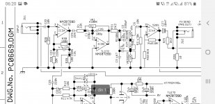
I did a little bit of research on soft clipping. Now there are two diodes in parallel to the feedback resistor. And I placed the drive mix knob at the end of the distortion path.
In this schematic a 50 mV guitar signal is amplified to a 400 mV clipping signal. That should be OK as an input voltage for the power amp ?
Any thoughts ?


In this schematic a 50 mV guitar signal is amplified to a 400 mV clipping signal. That should be OK as an input voltage for the power amp ?
Any thoughts ?
You'll likely want a small cap in parallel with the clipping diodes.
If you are planning for a 50mV input which I take you to mean a guitar's passive pickups, then a 5532 in inverting mode is a ludicrously low input impedance. Maybe use a FET input opamp in non-inverting mode and increase the gain above unity so as to improve signal/noise sooner in the circuit.
If you are planning for a 50mV input which I take you to mean a guitar's passive pickups, then a 5532 in inverting mode is a ludicrously low input impedance. Maybe use a FET input opamp in non-inverting mode and increase the gain above unity so as to improve signal/noise sooner in the circuit.
There's no chance you're gonna get away with 10kohm input impedance for guitar pickups...1Meg is the usual input impedance and that's something more attainable with jfet opamps.Tl072 or opa2134 would be your best bet for input op amp.
https://www.diystompboxes.com/smfforum/index.php?topic=46201.0
https://www.diystompboxes.com/smfforum/index.php?topic=46201.0
Marshall valvestate 80 and others...there are plenty of schematics outhere...
Attachments
-
 Screenshot_20230118-062136_Word.jpg84.4 KB · Views: 166
 -
 Screenshot_20230118-062129_Word.jpg114.2 KB · Views: 154
 -
 Screenshot_20230118-062120_Word.jpg139.4 KB · Views: 149
 -
 Screenshot_20230118-062104_Word.jpg112.8 KB · Views: 146
 -
 Screenshot_20230118-062045_Word.jpg151.4 KB · Views: 170
 -
 Screenshot_20230118-061918_Word.jpg117.5 KB · Views: 160
Yes. Plagiarize plagiarize plagiarize!! Only, call it "research"....there are plenty of schematics outhere...
This thread may be of interest, especially the first few dozen posts:
https://www.diyaudio.com/community/...d-state-e-guitar-preamps.391513/#post-7156398
With the peak guitar voltage levels posted there and the rather low supply voltage of the circuit of the present thread, it would make sense to use a unity-gain FET op-amp buffer, then a volume control potmeter with a relatively low value and then the rest.
Research it is.Yes. Plagiarize plagiarize plagiarize!! Only, call it "research".
I´ve been biting my tongue from post #1 out of courtesy to a new member, but fact is, he has NO CLUE.
At all.
He needs to take a hard long look at, what? ... 20-30-50 commercial Guitar amps, to get a hint about what´s used and needed in the field.
Sadly, thanks to the current obsession with tubes, there are many books on Guitar Tube designs, but almost zero about SS designs, with the honourable exception of the excellent (and unique) book by Teemu Kyttala.
https://www.pdfdrive.com/solid-state-guitar-amplifiers-e24629428.html
or:
https://www.thatraymond.com/downloads/solidstate_guitar_amplifiers_teemu_kyttala_v1.0.pdf
It is generously downloadable for free, an impressive and very well researched book, and should be read at least 10 times, to "absorb" the main points.
And then a few simple commercial designs should be built, tested, tweaked.
And then maybe starting some own designs.
But ... but ... but ... that means to "plagiarize" ...... ???
Then what do you call randomly slapping together a couple gain blocks straight from "The Op Amp Handbook" or any similar source, plus a chipamp datasheet example?
To boot, with no clue.
At least he should have read the next chapter, because he seems to know only the inverting Op Amp configuration, which he uses everywhere..
Also making gross errors, such as what was noticed above: adding a 100 ohm resistor in series with TDA7267 output.
WHY?
Probably because OP saw many Op Amps use such a resistor, so why not?
Slowing down a little and starting with basics, universal principles, going step by step, etc. , never hurts and is the correct path.
Sorry.
Guitar headamp realm is smth that's been studied for 6... 7 decades now...There's not much to add to it if any, but it has its ways , far from the hifi world. When you hear a guitar player on the radio, he's most probably using a Marshall, Peavey, Roland cubes, Fender, Vox, Gibson, etc...but Marshall is the name of choice for any beginner to copy and understand how you get a crunch, what the types of drive essentially sound like...It's not really a lot to learn in terms of specific sounds...You'll easily get what a tube amp sound like opposite to solid state and now there's this digital thing that stole all essence from the bussiness.
I can hardly see how you're going to be original without even knowing at least 10 commercial designs and the differences between them.Understanding them completely is even a longer process.
I still have about half a cubic meter of guitar amp schematics on paper from 2004...2010 when I'd go to an internet cafe put my disk in the computer then go with it to a printing shop.I understood how most of these schematics work 5...10 years after i have finished with cloning...didn't have a usb stick back then.
Last edited:
Actually there is an original way..I remember 17..18 years ago reading about an FM guitar amplifier where the preamp consisted of a feequency modulated system by the strings, then an fm demodulator was added . Not sure you wanna go that way though🙂
About the op amp with diode clipping in the feedback: look up the Tube Screamer schematic, or the Timmy overdrive. They use this concept, but important for a good sound (subjective of course): signal goes into non inverting input. And, you need some kind of tone control, especially for high frequencies. Also, as I can testify from personal experience, an op amp with low slew rate sounds very well here. I use the good old 741, and it rocks!
Thank you everybody for your replies. I really appreciate.
Last year I built myself a passive 8 inch speaker cab to use it with an external amp. But then I thought, why not integrate a small amp into the cab and use it for both guitar and audio.
I watched tutorials, read op amp data sheets and started with an LM386, LM380, TDA2050, TDA7267, NE5532, resistors, caps and a breadboard. The TDA2050 was desoldered from a Fender modelling amp.
I found that the inverting configuration works better than the non inverting. Somehow the bias voltage on the negative input didn't work. It worked when the bias was connected directly to the input signal though. But in general the inverting configuration was more stable. I'll look into it.
I also found out that I need a buffer stage before the volume control. The first designs had a lot of hiss and radio frequency interference. But with an input resistor and/or 47 nF cap to ground it was much better. However, the cap to ground next to a pot can work like a low pass filter. The output resistor helps with reducing noise as well.
I played around with different feedback resistors, op amps, etc. and watched the input and output signal on the scope.
The first design that worked okay, was with a NE5532 as a buffer and a LM380, 386 or TDA as a power amp.
Maybe I should have posted this as an introduction 🙂
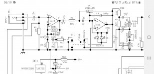
I redesigned the input stage. It now has a gain pot and an input impedance resistor.
On the breadboard and on the scope it looks and sounds okay.
However I don't notice any difference in tone with or without the 470k impedance resistor. No tone difference with a guitar tone and no visible difference on the scope. The guitar has 7 k passive pickups.
After comparing a few other schematics of overdrive pedals that resistor seems to be a common component in the input stage.
Are there other parts that are crucial for creating the right impedance?
This 470K resistor keeps C1 at defined voltage between plates, else you will ear a loud POP sound when inserting the guitar pickup with the amplifier powered on. I don't know anything about guitars and pickups, but as engineer I can affirm that is good practice to put it there.
I also suggest to put inverse biased diodes between input and both supplies in order to prevent static electrcity to blown the first stage when inserting the plug(s).
I also suggest to put inverse biased diodes between input and both supplies in order to prevent static electrcity to blown the first stage when inserting the plug(s).
- Home
- Amplifiers
- Chip Amps
- Guitar chip amp design - opinions