Hi all,
with the excuse of the energy costs, I thought about a possible solution to keep the consumptions of a class D and the harmonics of a SE class A.
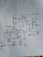
Thinking about the classic triode with CCS load, I imagined to rotate the curves (vertical) and the load line (horizontal) by 90° and ended up with a nfet (horizontal curves) loaded by a shunt cascode (vertical load line).

Voltages are very low, so a simple 7824 and 7812 can supply the needed voltages.
Output impedance is quite low (500 Ohm), miller is absent so bandwidth is very high, gain is 7.6 dB and the only feedback is the cathode resistor (that also sets the working point of the nfet).
Here comes the question to tube experts: I can't measure the harmonics, but seems to sound well, it's super easy and harmonics on simulation are what I've always been told should sound fine, including the negative phase of the second harmonic and one order of magnitude between one harmonic and the next one.
This is with 100 mVp at the input and 240 mVp at the output:
This is with 1 Vp at the input and 2.4 Vp at the output:
After that at the moment there's a cheap class D amp.
If tests will give good results on the full range speakers as well, I will try something better as power amp.
Thank you in advance,
Roberto
with the excuse of the energy costs, I thought about a possible solution to keep the consumptions of a class D and the harmonics of a SE class A.
Thinking about the classic triode with CCS load, I imagined to rotate the curves (vertical) and the load line (horizontal) by 90° and ended up with a nfet (horizontal curves) loaded by a shunt cascode (vertical load line).
Voltages are very low, so a simple 7824 and 7812 can supply the needed voltages.
Output impedance is quite low (500 Ohm), miller is absent so bandwidth is very high, gain is 7.6 dB and the only feedback is the cathode resistor (that also sets the working point of the nfet).
Here comes the question to tube experts: I can't measure the harmonics, but seems to sound well, it's super easy and harmonics on simulation are what I've always been told should sound fine, including the negative phase of the second harmonic and one order of magnitude between one harmonic and the next one.
This is with 100 mVp at the input and 240 mVp at the output:
Code:
Harmonic    Frequency     Fourier     Normalized     Phase      Normalized
 Number       [Hz]       Component     Component    [degree]    Phase [deg]
    1       1.000e+03    2.419e-01    1.000e+00      180.00°        0.00°
    2       2.000e+03    4.182e-04    1.729e-03       90.00°      -89.99°
    3       3.000e+03    3.841e-06    1.588e-05     -179.89°     -359.89°
    4       4.000e+03    3.074e-08    1.271e-07      -85.22°     -265.22°
    5       5.000e+03    2.164e-08    8.943e-08      -23.29°     -203.29°
    6       6.000e+03    1.286e-08    5.315e-08     -155.36°     -335.36°
    7       7.000e+03    2.308e-08    9.542e-08      114.68°      -65.32°
    8       8.000e+03    7.136e-09    2.950e-08      103.05°      -76.94°
    9       9.000e+03    1.315e-08    5.436e-08       12.36°     -167.64°
Total Harmonic Distortion: 0.172874%(0.172872%)
This is with 1 Vp at the input and 2.4 Vp at the output:
Code:
Harmonic    Frequency     Fourier     Normalized     Phase      Normalized
 Number       [Hz]       Component     Component    [degree]    Phase [deg]
    1       1.000e+03    2.407e+00    1.000e+00      180.00°        0.00°
    2       2.000e+03    4.321e-02    1.795e-02       90.00°      -89.99°
    3       3.000e+03    4.079e-03    1.694e-03     -179.99°     -359.99°
    4       4.000e+03    3.596e-04    1.494e-04      -90.01°     -270.01°
    5       5.000e+03    5.066e-05    2.104e-05        0.02°     -179.98°
    6       6.000e+03    4.319e-06    1.794e-06       90.10°      -89.90°
    7       7.000e+03    8.893e-07    3.694e-07     -179.53°     -359.53°
    8       8.000e+03    4.852e-08    2.015e-08      -88.82°     -268.82°
    9       9.000e+03    1.557e-08    6.466e-09       25.25°     -154.74°
Total Harmonic Distortion: 1.802813%(1.802812%)
After that at the moment there's a cheap class D amp.
If tests will give good results on the full range speakers as well, I will try something better as power amp.
Thank you in advance,
Roberto

I've receipt a notification on an user writing it will not deliver power, even if now I don't see the post anymore.
Yes, I know, that's why I've writtren I add a class D amp after it. It is a preamp to give the harmonics of a triode in a cheaper and simpler way.
I just would like to know from more experienced people if the harmonic behaviour at low and high levels is what is expected from a SE tube amp.
A good thing is that biasing the nfet colder (higher source resistor) will give a soft clipping on the upper part of the wave. Lower clips very abruptly.
I suggest you simply build the FET stage, period, which will obviously add its own quirks, specially non linearity and distortion, and use that signal to drive a Class D amp.
Guitar players do it all the time, specially so called Hybrid amps (Marshall Valvestate) where they use a 12AX7 stage (hint, a real tube, so "better" than your Fet stage) which later gets SS power amplified.
Remove Q1 and R5 and add a much needed coupling capacitor.
Which you missed in your current schematic.
For peace of mind, re-run all simulations and compare.
???? There was no question asked at all. However you can replace R3 with a 6AL5 diode to get more vacuum tube flavour.Here comes the question to tube experts
I'm sorry, but this is not the point JMF.I suggest you simply build the FET stage, period, which will obviously add its own quirks, specially non linearity and distortion, and use that signal to drive a Class D amp.
This is not a guitar amp and it is not designed to make a cello sound like EVH.Guitar players do it all the time, specially so called Hybrid amps (Marshall Valvestate) where they use a 12AX7 stage (hint, a real tube, so "better" than your Fet stage) which later gets SS power amplified.
I'm sorry but you totally missed how the line stage works, so how can you say it is worst?
I'm not saying it is not worst, butthat you should understand how it works before judging.
Q1 is the key point of the behaviour of the line stage, as I wrote in the first post.Remove Q1 and R5 and add a much needed coupling capacitor.
Which you missed in your current schematic.
No need, I already know how it will sound and I don't like it.For peace of mind, re-run all simulations and compare.
???? There was no question asked at all. However you can replace R3 with a 6AL5 diode to get more vacuum tube flavour.
Here comes the question to tube experts: I can't measure the harmonics, but seems to sound well, it's super easy and harmonics on simulation are what I've always been told should sound fine, including the negative phase of the second harmonic and one order of magnitude between one harmonic and the next one.
Hi indra1, my question was: the circuit in its basic version sounds good, and simulations give the shown values. Are those harmonics ratios in simulations (I cannot measure real ones) similar to a good tube SE amp? Thanks
I don't think it is a folded cascode, but I would like to ask you confirmation about it by describing how the circuit works.It's a good thing to see a folded cascode analysed for distortion patterns...Why not?
Q1 keeps J1 drain voltage stable, so the voltage at J1's gate changes the current flowing through J1.
R2 is a CCS due to the constant voltages at both its sides.
The current through R2 can pass through J1 or R5, the latter will then become the output voltage.
If you want to increase the gain and accept an higher output impedance, refer the grounded side of R5 to a negative voltage and increase its value.
This is why I said that curves and load line are like a CCS loaded triode rotated by 90°.
Please JMF, instead of taking it personally, try to re-read what I wrote and the explanation.Never saw so much self-contradicting in a post, it must be some kind of record.
Thanks.
IMO this resembles the cascode circuit but with top BJT PNP. Never seen cascode as power amplifier except in TV and PC monitors as video output stage (really litte power to drive CRT cathodes but at 60V pk)
I'm sorry to read that after two years from the last time I replied to you, you still attack every post of mine without reading it.Another virtual circuit with a non sense
Walter
I'm sure that without the keyboard in between, the lion would leave the space to a more reasonable discussion.
Hi Osvaldo, happy to read you here. Please re-read my messages, it isn't the power amp, but the line stage that will use a class D amp after it.IMO this resembles the cascode circuit but with top BJT PNP. Never seen cascode as power amplifier except in TV and PC monitors as video output stage (really litte power to drive CRT cathodes but at 60V pk)
It is a cascode, but not the standard one. You can find my explanation here above.
Thus if this is a line stagen not to much power is wasted using true tubes. Perhaps you can build one using a kind of opamp using a single compactron 6BD11 for example.
I did such an amplifier for a Baxandall stage. No need for more thn 15 or 20W.
I did such an amplifier for a Baxandall stage. No need for more thn 15 or 20W.
Last edited:
- Home
- Amplifiers
- Tubes / Valves
- Suggestions for a non-tube line stage by SE tube expert