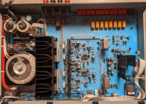
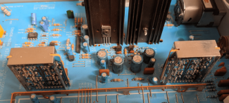
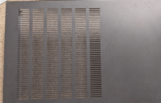
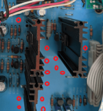
Vertical heatsinks on amplifier PCBs are a weakness since they dissipate heat poorly especially in a wide low chassis with insufficient ventilation. See in the attached photos where the NAD C320 is only partially vented on the top and even less on the bottom. The output stage has it's own shrouded heatsink which is slightly warm. The driver stage with the vertical sinks is somewhat hot. These two sections are under the vents. But the 18vdc discrete regulators are finger-burners. There are tiny holes in the PCB beside the regulator heatsinks which I suppose is intended to allow a wee bit of air to convection cool the heatsinks. Huh?
The C320 worked perfectly for thousands of hours until it began varying the audio volume intermittently. Such problems are difficult to troubleshoot. I need to fix it or visit the recycling depot. There are no obvious bad components but the internal heat dome is suspect.
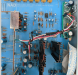
In addition to poor ventilation, the input voltage to the regulators is excessive (38vdc for 18vdc out). This is probably a design choice to work with the toroid which has only two secondaries. One is tapped to produce 38v and 48v, the other is low-voltage for a 7805. So the 38vdc remains. I decided to install a custom pre-regulator for that. It reduces the regulator P=ExI value from 2.4 watts to 0.72 and relocates 1.68watts to the chassis metal on the mainboard perimeter. The amp works fine with 24vdc, not 38vdc, driving the regulator.
There is an option for additional cooling. Place a tiny 12vdc fan on the chassis cover such that it blows across the vented area. This is effective since it creates low pressure over the chassis and draws out some heat.
The C320 worked perfectly for thousands of hours until it began varying the audio volume intermittently. Such problems are difficult to troubleshoot. I need to fix it or visit the recycling depot. There are no obvious bad components but the internal heat dome is suspect.
In addition to poor ventilation, the input voltage to the regulators is excessive (38vdc for 18vdc out). This is probably a design choice to work with the toroid which has only two secondaries. One is tapped to produce 38v and 48v, the other is low-voltage for a 7805. So the 38vdc remains. I decided to install a custom pre-regulator for that. It reduces the regulator P=ExI value from 2.4 watts to 0.72 and relocates 1.68watts to the chassis metal on the mainboard perimeter. The amp works fine with 24vdc, not 38vdc, driving the regulator.
There is an option for additional cooling. Place a tiny 12vdc fan on the chassis cover such that it blows across the vented area. This is effective since it creates low pressure over the chassis and draws out some heat.
Attachments


Too much power dissipation in the regulators. And no vents over the heat sinks for them. Eventually you end with with a cooked and discolored PCB. The PCB could use more of those holes too - or a bit of clearance between the board and heat sink. At least it’s not inside a sealed subwoofer enclosure where they tend to make the same “mistakes” and it gets way hotter.
Is part of the problem insufficient clearance underneath due to shallow feet and not enough holes in the bottom plate of the case?
Why not cut or drill more holes in the casing above the heat sinks?
I did that with my old Yamaha C-80 pre-amp, simply drilled a lot of 10mm holes and added a secondary shield over the holes to stop the possibility of people inadvertently covering these holes.
Why not cut or drill more holes in the casing above the heat sinks?
I did that with my old Yamaha C-80 pre-amp, simply drilled a lot of 10mm holes and added a secondary shield over the holes to stop the possibility of people inadvertently covering these holes.
Yes I could add a transformer to give reasonable input to 18v regulators but another idea comes to mind. There is an 8.3vrms secondary and a 7805 for control circuits. I am going to modify it as a voltage doubler to give almost 20vdc for a 7812 to power a small internal fan.The better option is to add a small 2 x 18V toroid transformer. No fan needed.
The core problem is no air flow to take away the internal heat. I reduced power to the regulators but they still rise to more than 50C. I will do some measures with a MCU remote temperature sensor to better understand.
There is only a small grill in the bottom plate below the toroid. The mainboard blocks any air flow from below except for the output stage which has a heatsink chimney.Is part of the problem insufficient clearance underneath due to shallow feet and not enough holes in the bottom plate of the case?
Why not cut or drill more holes in the casing above the heat sinks?
Heat from the regulators must flow sideways which is not natural. It is baking the electrolytics. Heat is the enemy of electronics
Amps which are passively/convection cooled must have an air flow structure or external heatsinks. I am going to add an internal fan to this old NAD.
Run the 12V fan off a little lower than 12 volts. Just use the rectified 8.3 directly. That voltage doubler and 7812 are just going to add more heat, and more than likely you won’t want to run it full speed.
Proper convection would require holes above and below the heat sinks. Bad designer, whack. And yes, those little electros look baked. This is where you need 105C parts. They’re not THAT expensive.
Proper convection would require holes above and below the heat sinks. Bad designer, whack. And yes, those little electros look baked. This is where you need 105C parts. They’re not THAT expensive.
I replaced a 2300uf cap in the 7805 circuit. It now gives 10vdc which runs the fan slowly. But I want more airflow.Run the 12V fan off a little lower than 12 volts. Just use the rectified 8.3 directly. That voltage doubler and 7812 are just going to add more heat, and more than likely you won’t want to run it full speed.
Put a mains powered fan, biggest that will fit.
And a 12-0-12 transformer, or 0-15, to feed the 7812, which may not be highly rated in load.
Some track cutting will be needed.
And a 12-0-12 transformer, or 0-15, to feed the 7812, which may not be highly rated in load.
Some track cutting will be needed.
The fan I plan to evaluate is only requires 80maPut a mains powered fan, biggest that will fit.
And a 12-0-12 transformer, or 0-15, to feed the 7812, which may not be highly rated in load.
Some track cutting will be needed.
Or get a ball bearing type 24 VDC fan, mount it under or over the top grill.
You can put a mains powered fan, too...
That might work, and give you some idea of how big a fan is needed.
External forced ventilation may or may not be a hack, personal preference.
Old trick from P-4 days, people put 6" fans in the side panels of the computers, as the CPU ran hot during graphics, at a time when a 1.5 Ghz CPU with 512 MB RAM was state of the art.
Last edited:
If you will feed the 7812 from a different lower voltage transformer, then track cutting will be needed, to stop the 38 V supply to the 7812.
The 7812 is being asked to chop 38V to 12 V...so it heats up.
Or try the ceiling fan series capacitor trick to drop the 38V to a more decent level, use a 1 to 2 uF 400V in series.
Again, this is on AC side, not DC side to the 7812.
I prefer mains operated fans, simply because they are more reliable, lacking an internal DC-AC converter found in DC fans, which sometimes fails.
I first considered replacing or bypassing the entire 18v regulator section. Instead I removed the fusable resistors and used that to insert 317/337 as preregulator with 24vdc out. The prereg drops the regulator from 2.3. to 0.7 watt so some of the heat is moved to the side chassis where the prereg board is attached. But still the 18v regulator runs hot because there is zero ventilation. So next I am going to try a fan. I will try things until satisfied or lose interest.If you will feed the 7812 from a different lower voltage transformer, then track cutting will be needed, to stop the 38 V supply to the 7812.
The 7812 is being asked to chop 38V to 12 V...so it heats up.
The fan power is not related to the 38v or the 18v regulator.
My bad, fan power meant the size and air flow of the fan selected.
In terms of velocity and air delivery.
Nothing to do with the rail voltages.
In terms of velocity and air delivery.
Nothing to do with the rail voltages.
Yes that is what I also do. It helps. Fans are a plain nuisance in devices as everything gets dirty/dusty and the reward is noise. I can not understand people suggesting this being a solution. A solution is to take away the cause of the generated heat, a pseudo solution is to blow away the generated heat.
The suggested voltage doubler may be possible but please check current first. In the past I have seen this many times and the added transformer and larger heatsinks used to be my weapons of choice. Simple and effective, almost no drawbacks except costs (which seems to be the utmost important parameter to some). An "install and forget" passively cooled solution. No need to make it more complex than it is. When modified correctly those vents in the cover really are enough for the now only a few Watts.
* the heatsinks with very short fins in this NAD are so long that an extra heatsink with longer fins can easily be drilled and mounted to the existing ones.
Last edited:
Just a thought.
I'm not an amp guy but I know a little bit about heat flow; I've seen those heat sinks with a secondary panel/heatsink extrusion fitted to then to make a tunnel. Tunnels can be very effective ways of removing heat but that heat has to escape somehow so I still think more venting of the case is a decent solution
I'm not an amp guy but I know a little bit about heat flow; I've seen those heat sinks with a secondary panel/heatsink extrusion fitted to then to make a tunnel. Tunnels can be very effective ways of removing heat but that heat has to escape somehow so I still think more venting of the case is a decent solution
First it is a poor design, adding a fan is a repair solution, and a way to check.
The proper solution would be more vents top and bottom, and a larger heat sink placed in a way that allows convective air flow.
To that end, something may be done to increase the height from the case to the shelf, meaning taller bottom supports or feet.
My Kenwood amp has a large part punched out of the PCB where the heat sink is fitted, and slots above and below it in the case.
That is called proper design.
No. A solution is taking away the cause of the excess heat. No excess heat = no issues to solve.
Not taking away the cause of the excess heat and sticking a bandaid = mitigating the still existing issues + adding new issues.
Proper design is reducing heat as much as possible by design and needing only a minimum of ventilation. NAD stuff often is mediocre by design. If NAD had not reduced transformer cost they could have added 2 x 18V windings and no excess heat issue would have existed.
This very same design error has been made by many British brands but also by Sony, Marantz, Akai (AM-U5/7), Denon (DA-500) etc. It is sacrificing longevity for lower cost. I recognize it from kilometers distance. In bad cases the regulators/transistors manage to desolder them selves and sometimes even insulation sheets have been omitted which you discover by accidentally touching heatsinks while measuring.
Last edited:

- Home
- Amplifiers
- Solid State
- Hot Heatsinks In Vintage Amps ... Such As NAD C320