[ Moderator Edit: This thread split from here - https://www.diyaudio.com/community/threads/problem-with-long-tailed-pair-phase-inverter.320241/ ]
I'm posting this question here because it is very similar to what is posted here. Hope that's ok.
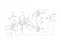
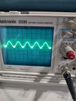
I've got this circuit breadboarded. Without the 12W6 output section connected, with a 1KHz input I can get nice equal sine waves from both outputs of the phase inverter at about 150VP-P before clipping. When I connect the output section there is some kind of oscillation that happens at about 50VP-P, Looks like the attached photo. The first section phase splitter oscillates at about 5VP-P higher that the second section. I like to get some help figuring this out.
Moderator Edit: This thread split from here - https://www.diyaudio.com/community/threads/problem-with-long-tailed-pair-phase-inverter.320241/ ]You need to pass a little bit of current through the 6N1P and some voltage across it. I chose around 3mA for each triode and 100V across the anode and cathode. You can push your B+ to 300V as long as the anode to cathode doesn't see much over 250V during operation as the tail resistor will eat (drop) quite a bit of voltage across it...
You didn't specify what output tubes you plan on driving with this.
I'm posting this question here because it is very similar to what is posted here. Hope that's ok.
I've got this circuit breadboarded. Without the 12W6 output section connected, with a 1KHz input I can get nice equal sine waves from both outputs of the phase inverter at about 150VP-P before clipping. When I connect the output section there is some kind of oscillation that happens at about 50VP-P, Looks like the attached photo. The first section phase splitter oscillates at about 5VP-P higher that the second section. I like to get some help figuring this out.
Attachments
Last edited by a moderator:
As shown output tubes are biased at -30V, should be able to drive up to 60Vp-p, but you can drive to 50Vp-p and no clipping is seem but oscillation already set in 10vp-p below clipping. I suggest you check the bias level (-30v or just -25v.). It seem to be the oscillation is due to transformer ringing which may settle if gNFB is applied or some snubber circuit is required in the output.
Thanks for the reply. I tried up to 20dB of gNFB with no change in the oscillation. The output tubes are biased at ~32-33V, normal variation in the 4 tubes.
Do you have a suggestion concerning the snubber?
Do you have a suggestion concerning the snubber?
I like to get some help figuring this out.
Are you doing the scope checks with a 8R dummy load, or none. Instability can happen without a load on the OPT.
https://music-electronics-forum.com...ubber-kits-any-experience?p=719041#post719041
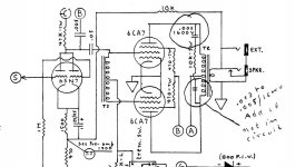
https://music-electronics-forum.com/filedata/fetch?id=849542
One is on the primary as attached, the other is on the secondary 0.1u-0.47u with 47-100 ohms in series.
https://music-electronics-forum.com/filedata/fetch?id=849542
One is on the primary as attached, the other is on the secondary 0.1u-0.47u with 47-100 ohms in series.
Attachments
Last edited:
Yes, I have a dummy load attached.
Is your 280v inverter supply well decoupled from the B+ with its own filter? A 10v difference seems a bit close for good decoupling.
Ok great, thanks. I'll try that in the morning.
One further development, with only the first section of the phase splitter (41.7k load) connected to one of the output tubes, there is no oscillation before clipping on that section.
One further development, with only the first section of the phase splitter (41.7k load) connected to one of the output tubes, there is no oscillation before clipping on that section.
I believe it is, I could be wrong. The power supply is C-L-C-R-C-R-C, 100u-5H-220u-(290V)-330R-100u-(280V)-1K-56u-(270V)Is your 280v inverter supply well decoupled from the B+ with its own filter? A 10v difference seems a bit close for good decoupling.
Gnfb resistor should have a small cap in parallel to reduce ringing (check the square wave response).
Where are your 1k grid stopper resistors on the 6N1P grids?
Wire them very close and directly to the 6N1P socket grid tabs, and then connect the junction of the 220n and 470k to the other end of the 1k grid stoppers.
Give it a try.
Leave those in, even if it does not fix the problem.
Next,
If the grid stoppers do not fix the problem, then increase the IXYS gate resistor from 100 Ohms to 470 Ohms, or even 1k Ohms.
Happy fixing, Happy Listening!
Please report back the results.
Last edited:
No improvement or change with 1k grid stoppers on the 6N1P, or 1k IXYS gate stopper, or snubber circuit across the OT primary/secondary.
I do find it interesting that the oscillation only sets in when I connect the non-inverting section (47k load). The inverting section works without oscillation.
I do find it interesting that the oscillation only sets in when I connect the non-inverting section (47k load). The inverting section works without oscillation.
I understand that without output tubes iis OK , but it's not clear if oscillations appear only with NFB applied or not ... this is the number 1 question/test that have to be asked/done .
Negative feedback is not connected. I did try up to 20dB of gNFB to the first stage as shown on the schematic. Output reduced accordingly but oscillation remained.I understand that without output tubes iis OK , but it's not clear if oscillations appear only with NFB applied or not ... this is the number 1 question/test that have to be asked/done .
As was said before the voltages 290V - 280V - 270V are too close , only 330ohm resistor is not enough between the output stage and phase inverter and then 1K for input stage is not enough either
Look at other schematics , something like 290V - 250V - 200V is normal
Look at other schematics , something like 290V - 250V - 200V is normal
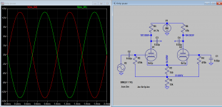
This is a stereo amp. Both channels exhibit the same behavior, +/- a few volts. I installed new 6N1P in each channel. The channel I'm working on now 191/196, the other channel 193/198.Can you try another 6n1p? The 2 plate voltages 200/190, a difference of 10V, where my sim shows only 187/185, only 2 volts diff. Has this tube section gone weak?
Yes, gate stopper is 1k now.Increase the gate stopper resistor value in the 10M45S?
- Home
- Amplifiers
- Tubes / Valves
- Long Tailed Pair phase inverter Oscillation