I kind of like the vintage look of this loudspeaker. A description is for example here https://electravolt.blogspot.com/2017/12/western-electric-ta-7331-baffle.html?m=1
I am now building a prototype of a large 3D printed horn for DCX464 and this style of cabinet would be a good match visually. Not so sure about performance, that is why I started this thread.
I see it as a sort of H baffle and I wonder:
I have Yamato YS-500 open back speakers with Eminence Deltalite 2515 and they measure almost flat in room down to 30 Hz when placed accordingly. So I would think the low end should not be a problem. I am more afraid of the front and back chamber resonances. I think the Deltalites could work fine even though the original driver was 12". I aim for the crossover to be somewhere in the 300 - 400 Hz range. Any comments will be appreciated!
I am now building a prototype of a large 3D printed horn for DCX464 and this style of cabinet would be a good match visually. Not so sure about performance, that is why I started this thread.
I see it as a sort of H baffle and I wonder:
- how high would it be usable before getting some bad resonances.
- how low would it perform with and without EQ
- what would be the parameters required for a suitable driver and which of the modern PA drivers to use
I have Yamato YS-500 open back speakers with Eminence Deltalite 2515 and they measure almost flat in room down to 30 Hz when placed accordingly. So I would think the low end should not be a problem. I am more afraid of the front and back chamber resonances. I think the Deltalites could work fine even though the original driver was 12". I aim for the crossover to be somewhere in the 300 - 400 Hz range. Any comments will be appreciated!
Hi pelanj,
you might want to try ask here: https://hifihaven.org/index.php?threads/ta-7331-a-here-we-go.6461/.
Also another member there, Tsingtao_1903, also uses it.
Kindest regards,
M
you might want to try ask here: https://hifihaven.org/index.php?threads/ta-7331-a-here-we-go.6461/.
Also another member there, Tsingtao_1903, also uses it.
Kindest regards,
M
Actually a BP6P, so sim in HR or similar with a (very?) lossy vent should give a 'good enough' idea of how your driver will perform.
Any measured response, etc., plots to compare to?
Any measured response, etc., plots to compare to?
@mefistofelez Yes, I am a member there, too. His scaled down version looks great. But there guys are using mostly vintage stuff I cannot get in CZ easily.
@GM So the BP6P model in Hornresp would give an idea? Do I understand it correctly I should make a model with a vent with the same cross section as the chamber cross section, both front and back? I found an old measurement in listening position, I will post it in a while.
@GM So the BP6P model in Hornresp would give an idea? Do I understand it correctly I should make a model with a vent with the same cross section as the chamber cross section, both front and back? I found an old measurement in listening position, I will post it in a while.

You can't sim a bunch of tilted up slats in any speaker program TTBOMK, so AFAIK all you can do is show some acoustic resistance due to them. If they're all adjustable, then lots of tuning options.
Hmm, I meant any TA-7331-A measurements.
Hmm, I meant any TA-7331-A measurements.
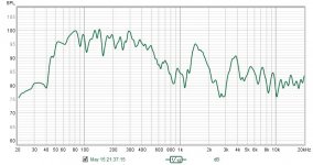
I see🙂 I posted these to show a reference I would like to reach in this form factor
I am just considering building one - will there be cancellations (or other negative things) related to width, height and depth of the front chamber? It feels to me there will be some. IMHO the both front and back will resonate like a short TL. I will try to simulate as a compound horn with straight walls - I got some nice (theoretical) results in the past for compound midbass horns if the ratio of the front and back depths was correct.
One of the nice things about this is the depth of the front chamber allows for time alignment of the voice coils with the right horn length with the mouth aligned with the front edge.
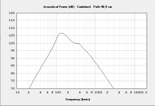
This is the Hornresp record I came up with. I just tried some random drivers from the database and the Deltalite II 2515 does seem to work OK. The back part is open now, so I would think that the lower peak would be a bit less with back chamber damping. I still see a strong need for a subwoofer, so I am actually in doubt if this large cabinet is worth building. Maybe some more low extension can be gained from a good placement? I also tried a 2/3 scaled version, not really better.
I also tried to simulate a similar sized, easier to build H frame open baffle (both symmetrical and asymmetrical chamber lenghts). And as expected, it is pretty similar in response. It does not look as cool, but would serve the purpose as well.
I also tried to simulate a similar sized, easier to build H frame open baffle (both symmetrical and asymmetrical chamber lenghts). And as expected, it is pretty similar in response. It does not look as cool, but would serve the purpose as well.
Attachments

will there be cancellations (or other negative things) related to width, height and depth of the front chamber?
HR has option to work with unmasked chamber resonances. Have you tried that option?
In the compound horn and H baffle model, there is no chamber. I have this option enabled to prompt - and it does not prompt. Direct enabling does not do anything, too.
I was looking at the in room measurements at HiFi Haven and there is clearly some gain from close to wall placement, that cannot be modeled in Hornresp AFAIK. I think one of the points of the 7331 is the asymmetrical placement of the woofer in the front chamber. The large H frame form factor is still somehow tempting me to build a test box from scrap materials I have laying around or maybe some cheap OSB/particle board. Step 1 will be to create a 3D model from the original drawing, step 2 modifying for available wood🙂 I have a pair of vintage AlNiCo 12" woofers that could work fine there.
No, just theoretical pi spaces, which in my room, corner loading most closely matches 1 pi. 🙁
Loaded it and was a bit surprised that it only loaded over a narrow BW, but then remembered that at the time of this early a cab that they were only interested in the speech BW, so doing a modern OB for a high Qt driver to mimic the pioneer's matching impedance systems makes sense.
Actually, spec wise a guitar driver is closest except ~0.7 Qt or needs a matching impedance amp.
Last edited:
While playing with Hornresp, it seems that there are some benefits to making the front and back chamber different lenght and cross section. I am now trying to find some nice balance between loading and size. Ot of the woofers I have, the Deltalite simulates the best.
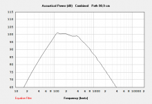
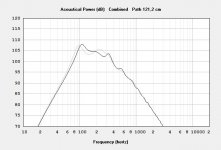
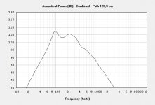
These are my thoughts and results. The U-Frame model dimensions are based on the YS500 clones I have. It looks like a rough fit to the near field response. So in theory, the proposed 88 cm deep H frame should work fine. I chose 1:3 depth ratio, which is in my opinion a good compromise. The first file is with the front chamber deeper. If I reverse the chambers to follow the 7331 pattern (which might be more reasonable anyway), it looks like it would work well with a crossover to a subwoofer.
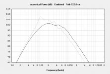
This got me thinking. I originally considered building Volvotreter's conical midbass horn. This thing would be much easier to build, with not much larger footprint and it would also bring the mid-high horn to the correct height. And there seems to be around 5 dB gain compared to a flat baffle (if my sims are right - last picture shows comparison).
This got me thinking. I originally considered building Volvotreter's conical midbass horn. This thing would be much easier to build, with not much larger footprint and it would also bring the mid-high horn to the correct height. And there seems to be around 5 dB gain compared to a flat baffle (if my sims are right - last picture shows comparison).
Attachments

That is my build thread on Hifi Haven
The TA baffle is a very well braced u baffle, the two chambers are about the same size the front taller and a shorter depth than the rear.
I have tried a few different 12 inch woofers all vintage.
The Altec 414 is a really good match, the Rolla driver make good bass in it.
I don't use any e.g., but with a modern driver it could work well., but my goal was trying to be truer to the orginal, knowing I could never dream of affording the real WE stuff.
I also am using a sub the fill in below the TA baffle.
I hope this helps.
Cheers
Ed
Thank you very much for chiming in, Ed. Your build inspired me to think about this - based on the sims, the original size would definitely work well and looks very good. Also your measurements posted there are very informative. I will definitely build a variation on this topic - as one of the contestants being able to fill between the horn and sub. The plain old (bass reflex or sealed) box would work, but is boring. The other three candidates will be a SLOB, three different front horns and a paraflex box.
So I bought some wood today and made a sketch. The box can be built using 3 pieces of 2050 x 625 x 18 mm OSB subfloor panels. The split side panel will benefit from the tongue-groove connection. The tongue on the higher panel will be cut off flush above the joint (the tongue is not shown in the drawing).

The dimensions are based on the simulation marked as H-Frame Reversed. The "dead" volume behind the speaker baffle is a) to provide enough space for horn placement, b) to cut some holes as handles, I estimate the handles could be pretty close to the center of gravity when the driver is installed. No bracing planned for now. If it works fine acoustically, it will get the proper 7331 bracing. If I understand the function of the louvers on the original, they should damp the back chamber a bit. Playing with filling in hornresp shows that If I put in a pillow or two to the back, they will lower the 100 Hz peak.
Although quite large, the space on the back resonator can be used for hiding the amplifiers, each side will need 3 or 4 channels.
I am quite curious how this turns out.
While further playing with Hornresp, it looks like I can gain a few extra maximum dB and few Hz if I increase the back resonator heigh to 60 cm (the maximum size 3 panels of OSB will easily allow. It would loose some of the visual benefits. If I build it like that, would e.g. XPS filling be enough to make the back resonator size acoustically smaller? That way I would have some options for further tuning - by inserting various XPS boards into it. Is that worth trying out?
Edit: Another question, would it be of any benefit to place the woofer on the baffle with golden ratio (both x and y relative to the front resonator)? That would result in golden ratio placement in the x axis for the back resonator as well. The only drawback would be the need to build two mirrorred cabinets for stereo.
Edit: Another question, would it be of any benefit to place the woofer on the baffle with golden ratio (both x and y relative to the front resonator)? That would result in golden ratio placement in the x axis for the back resonator as well. The only drawback would be the need to build two mirrorred cabinets for stereo.
Last edited:
- Home
- Loudspeakers
- Multi-Way
- Western Electric TA-7331-A Baffle