Hello,
I receive my new pair of Bliesma M74B recently and would like to share some results.
While expensive I find that newcomer is a breakthrough in large dome medium driver for a long time. Hificompass did extensive measurements on those and all have been confirmed here also.
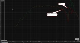
What I would like to share is the use of a passive twin filters (only two inductors and two capacitors to reduce somewhat the two main breakouts (around 13-17 kHz) of the beryllium dome.
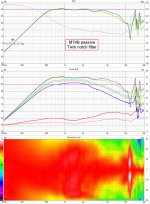
You will notice that the two peaks are reduced by about 10 dB but more important is the reduced third and fifth distortion figures.
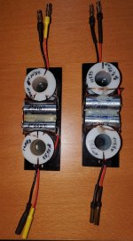
Of course at those frequencies, it is mandatory to measure exact values of the capacitors and adjust the inductance accordingly. I use 20 x 16 x 30 m coils that I found at a very low price on internet and 1 mm diameter enameled copper. I also use a RLC bridge to get values that were optimized via the wonderful VituixCAD software
I receive my new pair of Bliesma M74B recently and would like to share some results.
While expensive I find that newcomer is a breakthrough in large dome medium driver for a long time. Hificompass did extensive measurements on those and all have been confirmed here also.
What I would like to share is the use of a passive twin filters (only two inductors and two capacitors to reduce somewhat the two main breakouts (around 13-17 kHz) of the beryllium dome.
You will notice that the two peaks are reduced by about 10 dB but more important is the reduced third and fifth distortion figures.
Of course at those frequencies, it is mandatory to measure exact values of the capacitors and adjust the inductance accordingly. I use 20 x 16 x 30 m coils that I found at a very low price on internet and 1 mm diameter enameled copper. I also use a RLC bridge to get values that were optimized via the wonderful VituixCAD software
Attachments

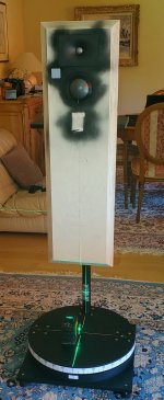
I did measure them at 1m on a 30 cm by 100 cm 30 mm birch plywood with a 45° chamfer front plate as seen on first image
I took +/-180° in 10° steps but as there is no box for the time being, I think +/- 90° are relevant here. Output voltage was about 1.3 V RMS and mic was calibrated at 94 dB. It's the raw driver only with the passive twin notch filter.
We can see an almost constant DI of +/-60° horizontal from 400 Hz to 2.5 kHz decreasing to 30° at 4 kHz. Of course it is somewhat different vertically due to the physical layout. If we combine these values with the exceptional low distortion, we have a winner here
I'm always reluctant to share subjective listening as it is a matter of taste but did some test with a sealed W024P sealed box and a quick and dirty 5 minutes active crossover (Hypex FA253) and I must say I'm impressed to say the least.
So in short very very promising
Attachments
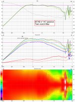
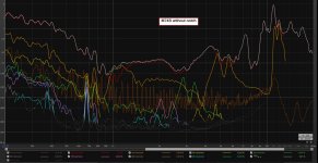
I am not quite sure how to read the distortion plots. The 2nd harmonic (red curve) and THD (white curve) war way higher than the fundamental (dark yellow curve). That can't be, so I guess something is wrong with that diagram, or we are missing some explanation of what is shown on the diagram.I receive my new pair of Bliesma M74B recently and would like to share some results.
Also, when looking at low-distortion drivers you might consider the non-linearity contributed by the (cheap) parts of your x-over / filter that you added to the setup.
What microphone did you use for these measurements? What is the non-linearity / distortion of the microphone?
Also, the measurement results from dispersion / directivitiy will be highly dependent on the baffle geometry. Can you repeat these measurements on a DIN baffle, so the data can be compared with other drivers?
EDIT: or did I confuse the 3rd harmonic with the fundamental? The colors / legend are hard to read. Also, what is the meaning of "Fundamental 63.8 dB" in the legend? Did the measurement process set the fundamental to 63.8 dB-SPL @ 1m at all test frequencies and then determine the harmonics at this level? [I don't think so, as the data look like they were taken using the Farina sweep method, but then the 63.8 dB number would be even more ambiguous, as the fundamental SPL would not be constant throughout the sweep.]
Last edited:
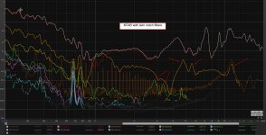
White is total harmonic distortion and while we can discuss about the absolute values, my goal was more to show the effect odf a serial passive notch filter to reduce third and fifth harmonic distortionI am not quite sure how to read the distortion plots. The 2nd harmonic (red curve) and THD (white curve) war way higher than the fundamental (dark yellow curve). That can't be, so I guess something is wrong with that diagram, or we are missing some explanation of what is shown on the diagram.
Cheap ? I use an air coil with OFC 1mm diameter copper and polypropylene capacitors . I think that with so low value (25 to 26 uH 1 mm diameter is enough. Don't you think so ?Also, when looking at low-distortion drivers you might consider the non-linearity contributed by the (cheap) parts of your x-over / filter that you added to the setup.
What microphone did you use for these measurements? What is the non-linearity / distortion of the microphone?
Earthwork M30 calibrated
Also, the measurement results from dispersion / directivitiy will be highly dependent on the baffle geometry. Can you repeat these measurements on a DIN baffle, so the data can be compared with other drivers?
I did it at home so no I can't compare with one made on a DIN baffle. Again you can compare with Hificompass own measurements
I had to reduce the mic preamp level by a little more than 20 dB for not to saturate gear input but M74B level was at 90 dB at 1m.
When I will have again time, I will redo distortion meaurements with step sines and will come back but I'm pretty sure of the effect of this very simple notch filter will have on third and fifth harmonics...
When I will have again time, I will redo distortion meaurements with step sines and will come back but I'm pretty sure of the effect of this very simple notch filter will have on third and fifth harmonics...
Sorry, I dont see much point for those noch filters.
Peaks are only 6-7dB above averige SPL and pretty high for dome of that size. If you cross with tweeter at 5 kHz with 18dB/oct slope thats 1,5 octaves to first peak slightly above 14 kHz, giving about 27dB attenuation. Enough to avoid any problems.
If you still feel you need to tame those peaks a bit, why not try single noch with higher bandwith/lower Q set at geometric center between peaks at 15,5 kHz.
Just my opinion, but I prefer simplicity.
Edit: first peak is main problem beacuse its more prominent and closer to xover point so less attenuated. With good choice for xover point and slope single noch at first peak should be enough.
Last edited:
Hello,
I receive my new pair of Bliesma M74B recently and would like to share some results.
While expensive I find that newcomer is a breakthrough in large dome medium driver for a long time. Hificompass did extensive measurements on those and all have been confirmed here also.
What I would like to share is the use of a passive twin filters (only two inductors and two capacitors to reduce somewhat the two main breakouts (around 13-17 kHz) of the beryllium dome.
You will notice that the two peaks are reduced by about 10 dB but more important is the reduced third and fifth distortion figures.
Of course at those frequencies, it is mandatory to measure exact values of the capacitors and adjust the inductance accordingly. I use 20 x 16 x 30 m coils that I found at a very low price on internet and 1 mm diameter enameled copper. I also use a RLC bridge to get values that were optimized via the wonderful VituixCAD software
Great data.
And thanks for sharing.
i disagree with comments posted so far.
Notch filters look very useful and useful low pass crossover point may be 2-4KHzdepending on phase alignment and directivity of matching tweeter.
Last edited:
You will not get the same results on third and fifth harmonics, that was the main purpose of this filter.Sorry, I dont see much point for those noch filters.
If you still feel you need to tame those peaks a bit, why not try single noch with higher bandwith/lower Q set at geometric center between peaks at 15,5 kHz.
Yes, I agree that the most significant is the first peak but I bought a bunch of those plastic spool so as I had to make the coil myself with only 3 layers or so, I did a twin notch...Edit: first peak is main problem beacuse its more prominent and closer to xover point so less attenuated. With good choice for xover point and slope single noch at first peak should be enough.
This is very useful data. The notch filters are of course a useful tool when working with this driver.
This is nice confirmation that series notch filters actually do suppress the harmonic distortion created by the usual distortion amplification found on drivers made with hard diaphragms.
Maybe 'cheap' was not the most appropriate term.Cheap ? I use an air coil with OFC 1mm diameter copper
I was not referring to the wire diameter. This mostly just determines DC resistance, which is not an issue here.
I am more thinking about the mechanical stability of the coils, which does affect the linearity (i.e. distortion) quite a bit.
There will be an internal separation between M74B & T25B from other drivers (twin 8" drivers) and epoxy is an easy fix for that, don't you think so ?I am more thinking about the mechanical stability of the coils, which does affect the linearity (i.e. distortion) quite a bit.
I am not sure I understand. What do you mean by internal separation, and how would that reduce the mechanical vibration of the coils? The current running through the coil will induce magnetic forces, which will act on the windings. Using coils with a more rigid construction helps to reduce the vibration an the corresponding non-linearity.There will be an internal separation between M74B & T25B from other drivers (twin 8" drivers) and epoxy is an easy fix for that, don't you think so ?
OK, internal separation will isolate the two drivers from internal pressure inside the cabinet and I think that epoxy could fix windings vibrations you are talking about. Anyway I don't think coil non-linearity has the same order of magnitude in regard with distortion improvement.
Maybe, we can go back to the subject the very nice M74B and passive serial notch filters to tame some breakup distortion
Maybe, we can go back to the subject the very nice M74B and passive serial notch filters to tame some breakup distortion
Mixing active and passive, best of both world.
Great paper from Purifi Audio about it :
https://purifi-audio.com/wp-content/uploads/2022/03/220211_R05-Notchfilter.pdf
Thanks for sharing!
Without going OT, what driver(s) will complement this amazing duo?
Edit : OK 😉 https://www.diyaudio.com/community/...ifi-woofer-speaker-builds.352063/post-7038616
Thanks Jaypee for that article link, it clears things alot. It looks like "secret" is in fact that series notch, in its bandwith, acts as high impedance source for the driver and feeding the driver with high impedance is the main mechanism for reduction of distortion.
I for one am eager for subjective impressions; how it compares to...anything!I'm always reluctant to share subjective listening as it is a matter of taste but did some test with a sealed W024P sealed box and a quick and dirty 5 minutes active crossover (Hypex FA253) and I must say I'm impressed to say the least.
- Home
- Loudspeakers
- Multi-Way
- Bliesma M74B three inch dome driver