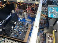
Got this nice non-working Sherwood HP-2000. Got the preamp side working quite nice. The power section is a total wreck. One driver board is toast and the other one produces distortion and sets off the peak LED indicator. For now, I have taken out all the power section components and temporarily wired in circuit a class D Wondom power amp of the same rating (125 watts vs. 120 watts). Sounds wonderful!
But should I tackle rebuilding these driver boards and packing new outputs trannies (did one already)? I will need to match the input pair, pre drivers, and drivers to current transistors and think I will use the LME 48710 instead of the RCA3100 op amp.
I may just skip all this and go to a higher powered D class amp and call it a day.
I did calibrate the power meters with the new class D amp and got about 100 watt out of it with ease.
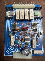
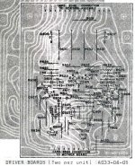
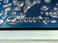
Some pics...I am sharing this thread as there is little info on these Sherwood nice vintage units. Although the driver board looks like it started a house fire, there is quite a bit of good left in it. I have highlighted in red the resistors that cooked off.
But should I tackle rebuilding these driver boards and packing new outputs trannies (did one already)? I will need to match the input pair, pre drivers, and drivers to current transistors and think I will use the LME 48710 instead of the RCA3100 op amp.
I may just skip all this and go to a higher powered D class amp and call it a day.
I did calibrate the power meters with the new class D amp and got about 100 watt out of it with ease.
Some pics...I am sharing this thread as there is little info on these Sherwood nice vintage units. Although the driver board looks like it started a house fire, there is quite a bit of good left in it. I have highlighted in red the resistors that cooked off.
Attachments

From my recollection of the Sherwood models, which may be like your experience of finding them to be total wrecks, there were lots of problems due to quality issues including the component types and ratings of semis so I think that if you like the sound with the Wondom modules inside, continue with those or similar which you may find already discussed in the class D forum here. It's also far cheaper and simpler than trying to restore an old, midfi product to something like its original state and to what purpose?
The sticking point is that these tiny class D modules use equally tiny fans for cooling at low cost and taking up minimal PCB real estate. They won't last forever and dust will build up, causing overheating problems sooner or later, as with any fan cooled system in a typical home environment. I'd look at other high quality class D modules for better cooling options or at least the potential to modify the cooling system for long-term reliability. The cost will be greater but there's little point in restoring something to a state that's going to be another set of problems to solve in the not-too distant future.
.
Last edited:
Put a ready made Class AB populated PCB. Can maybe use the outputs and the heat sinks.
The output transistors may be used elsewhere, if you decide to use other types.
Lot of aged components inside which may have been damaged, and are unobtainable..
Becomes like an old car, constantly needing minor or major maintenance.
Then all you got out of it is the cabinet, supply and pre amp. I hope you got it cheap.
Most of the British and American audio systems of that era were made on a very small scale, and used the cheapest parts.
Results were also like that, and most have stopped production.
Wikipedia:
Sherwood is a manufacturer of hi-fi equipment.
The company was founded 1953 in Chicago.
The company is currently under Inkel Corporation of South Korea, one of the largest AV receivers manufacturers in the world.
Another Korean maker posing as American...
Last edited:
Naresh, you're quoting internet references to the Sherwood brand today. When that amplifier was built, the brand was still owned by the original US Sherwood company and production was in Chicago or possibly subcontracted to Japanese manufacturers. A look at the pics shows the build style, PCB patterns, semis and components including a few Stackpole type carbon comp. resistors that you won't find in any east Asian product though.
Last edited:
The Japanese used the kind of foil patterns I saw in Elektor magazine, straight or 45 degrees, rarely 30 and 60.
No curved traces, and components on the other side of the foil.
So a look at the PCB told me it was not Japanese, and there were also flux residues, consistent with repair or hand soldering.
Components on foil side, old mask color and so on... distinctive.
And the cause for my remark that this was made in a small factory or workshop.
The op amp markings are not there, possibly removed, another give away, so you would be forced to go to their service center if you had a problem.
Most Japanese did not bother to do that.
There are RCA devices, one is GREEN in color in the first image, seems to a regulator, one is black, the other green.
Those are unknown to me, and RCA stopped making those a long time ago.
I would off hand date it to no later than 1970, given the amount of controls and the overall build.
The Japanese invaded the market later, and wiped out the competition.
In the camera market, they started sales through American companies in North America, and later came with their own brands.
I have no idea if the same happened in audio systems.
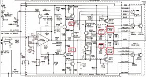
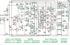
Those black and green driver transistors date to 1976, according to the date code. Fairly unremarkable today, just use MJE1503x series. Looks like the original outputs were changed out with the usual 15024/5, which is as good as anything for the purpose. According to the schematic, the original outputs were 2N5630/6030. They have higher GAIN above 8 amps compared to the 15024/5 (Not as rugged, but typically rugged enough in this application. I have used them without issue at this voltage). If you need new, MJ2119x can be used, which has a gain somewhere between the two. The lower gain outputs would stress the drivers and the resistors in the driver circuit (Which burnt up). If MJE1503x are used, they can take the additional loading without failure and their higher gain compared to the old RCA drivers will make up for lower gain outputs. Replace all 6 in each channel with these modern parts, swap out anything else that was collateral damage, and it won’t give any further trouble. If you want a bit more insurance, put bigger heat sinks on the drivers.
Dont go swapping out that input op amp unless you are prepared to re-engineer the frequency compensation.
Dont go swapping out that input op amp unless you are prepared to re-engineer the frequency compensation.

Thanks so much for the valuable information, this is more than I have found anywhere else! You all seem to indicate about a 1977-78 unit. It is made in the USA. Heavy solid knobs, nice layout.
Remind me if those balloon shaped caps are reliable or not. I am trying to chase one last glitch that I thought was a cold solder joint, it is rare, so not too worried.
Thanks wg_ski, with a recipe of input, drivers, and outputs I may just get motivated to give it a shot.
I am wondering if I could remove the "protection" components from the board as outlined in the schematic, it would simplify finding those diodes.
So were Sherwood's in this era considered hi-fi or more along the lines of affordable mid-fi?
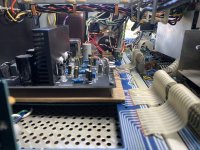
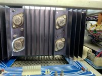
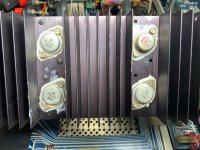
Here is the original condition of the heatsink and outputs, IIRC, they bench tested good. But, this was not the side that burned it.
Remind me if those balloon shaped caps are reliable or not. I am trying to chase one last glitch that I thought was a cold solder joint, it is rare, so not too worried.
Thanks wg_ski, with a recipe of input, drivers, and outputs I may just get motivated to give it a shot.
I am wondering if I could remove the "protection" components from the board as outlined in the schematic, it would simplify finding those diodes.
So were Sherwood's in this era considered hi-fi or more along the lines of affordable mid-fi?
Here is the original condition of the heatsink and outputs, IIRC, they bench tested good. But, this was not the side that burned it.
Attachments
Sherwood made guitar amps too, so I think their market was decent to good quality, not audiophile quality.
Don't remove the protection circuit unless the more experienced members tell you, it is another can of worms for the inexperienced.
Don't remove the protection circuit unless the more experienced members tell you, it is another can of worms for the inexperienced.
That “balloon” shaped cap is a tantalum - get rid of it and put in a standard electrolytic. Any good brand. The protection circuit does not need any special diodes. They are simply for current steering and literally anything (silicon) will work. Use 1N4004 or UF4004 and don‘t look back. 1N4148’s would work but can’t take as much abuse if something goes wrong. They do no need to be high speed, but it won’t hurt anything either. The protection transistors have collector-base capacitors which slow the action down to prevent instability. Speeding the diodes up won’t help anything. Transistors can take huge overloads for a few tens of microseconds at a time. Removing the protection entirely is ok for testing on a light bulb limiter - but have it in place and working when you go to hook it up directly.
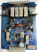
Nothing wrong with the original outputs in that channel too - MJ15003/4 are simply an upgraded premium 2N5630-series part. They take the full 140V (or more), have useable gain at 20A, and have higher rated SOA. If you open them up the dies look the same. That rogue 2SD424 was probably what a repair tech had on hand, and is THE best 4-MHz speed class part Toshiba ever made. I would have replaced both parallel units, however.
Some of the solder joints on that connector look a little fatigued. I’d re-solder it. Something like that could have been the cause of failure in the dead channel. If it happened on the vbe multiplier……
"Sherwood" was a model of Carlboro company. Not the same as the Sherwood company.Sherwood made guitar amps
Sherwood case looks awfully nice, and I have suspicions of class D stuff confirmed by post 2. Doomed to fail by the way the market works these days. You've got a copper banded transformer, something one can't buy these days.
I'd replace all those burnt 1/2 ohm resistors with 3 watt metal film resistors. Vishay, multicomp(newark) , welwyn have worked in my organs. Leave leads long and put them high up off the board, they run hot and will burn paper. Concur with drivers & output transistors wg ski suggested. I'd put more heat sink on drivers: one way companies went cheap that we can do better as amateurs. I've got surviving 2n5230 from the era in a M-2600. This chassis is a lot prettier than Peavey black on black. I've used MJ15003 in my 75 watt amps.
A fan mounted under those grills that is only on when the thermostat is hot could save future damage. 48 v ones can usually run off one of the rails. If you're running the amp that hard at a party, you won't hear the fan.
Last edited:
Thanks indianajo, was thinking of flameproof resistors where those igniters were, but maybe your suggestion is more robust.
Oh, BTW, it has these beautiful sides made of dark wood and an aluminum frame. Quite elegant, but make the amp unwieldy and will not fit in the rack. I will upload pics with them at some point.
Oh, BTW, it has these beautiful sides made of dark wood and an aluminum frame. Quite elegant, but make the amp unwieldy and will not fit in the rack. I will upload pics with them at some point.
Last edited:
Use mains operated fans, more reliable than DC fans, which convert DC to AC to turn the squirrel cage in the rotor.
And safer if it does fail short. Use a fuse...
Thermostat or constantly on as per your need, but AC fans, with either sleeve (quieter), or ball bearings seem to be more durable.
It is mentioned above that these are mid fi rather than hi fi units, and the frequency of the fault points to a careless design...seems a common fault.
Last edited:
They do make DC fans that are as reliable as a mains operated fan - but they cost $100 or more each. And run on 24 or 48 volts, not 12. They show up on the surplus market from time to time, which is the way to buy them. Papst, Rotron, IMC - one of the big names - and with some heft in the motor and decent bearings. The No-name cheapies with fan blades that weigh about 2 grams aren’t worth fooling with - they run for a couple months and die. AC operated are better than that and cost effective at the same time.
I salvage DC fans out of Allen Bradley & TB Woods industrial VF motor drives. Endless supply of blown up ones from my previous job. No trash in a industrial product. They are tiny but run for a decade in a dirty factory. Supply of blown VFDs should be endless but all I see on ebay is refurbished ones for $$$. Great MOS suppressors in those, also heat sinks.
I've put AC fans outside an amp case (inside an organ) but have been nervous about putting them inside. HUMMM.
I've put AC fans outside an amp case (inside an organ) but have been nervous about putting them inside. HUMMM.
Rexnord 110 x 38 mm fan (4 x 4x 1.5 inches), 22W, $4, 220 V sleeve bearing version, plastic blades. Ran 17 years in my molding machine, sometimes 24 x 7.
Ball bearing, plastic blade, would be $6 here, and the metal blade version is a bit expensive at $10.
Rexnord is a local Indian brand, the go to for panel builders here, the alternate is Commonwealth from Taiwan.
Papst is somehow not popular, could be price issue, could be reliability issue.
12 and 24 V DC, sleeve bearing, would be about that in 3 inch size, no metal blades in those models. Not seen any with ball bearings (did not look).
Buy an AC fan, from a good maker, get a lower flow model with the biggest blade size that will fit.
Slower fan means less noise, but most are 2600 -2800 rpm, so buy the lower noise or lower flow type, use at continuous run, as the heat sinks are smaller than needed.
Long term benefits in transistor life, and we do read here about sudden shortages of parts.
Update.
I took a tangent to another thread to formulate a good transistor recipe. I hope if it works, it will serve the next lucky (or not) HP-2000 owner. I have attached the proposed recipe, and parts are on their way from Mouser. Furthermore, I have been ordering parts from them for years, and I could not believe the cost of things now. A single low voltage Nichicon MUSE UES bipolar for $.47? Wow! Call me cheap, I don't care...
I will also take the igniter-feature resistors and upgrade them to 1 watt, lifting them off the board in preparation for future firework events (as suggested by indianajo).
To answer the question no one is asking: Yes! I am bothering to at least try to return the unit to its original state.
Thanks for the help so far, could not do it on my own.
I did take the factory original outputs out of the burnt channel, all test good on the bench. Hopefully, all the problem is contained in the driver board. Another clue is that all the fuses look original and are good.
Attachments
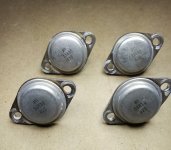
I found stressed output transistors can test fine at 1.5 to 2 v of a DVM or tester, but leak like sieves at rail voltage. I found that testing Iceo at 12 v predicts whicn ones will explode at 170 vdc. 12 v battery charger series 47k resistor series millamp scale of DVM. + to C - to E on npn, base open. Current =12v/47kohms, that is a damaged transistor.I did take the factory original outputs out of the burnt channel, all test good on the bench.
You can blow off this test if you use an AC current limiter into the power transformer, like a 60 w light bulb series the power cord. Measure voltage across emitter resistors at idle to detect leaky output transistors.
Reason I suggested 3 w resistors, modern vishay 600 mw 1 w resistors withstand that wattage at 200 C or so. The resistors will stand it, your PCB won't. You can tell which ones are the new material, they have a voltage rating below 200 v, which means they are tiny. 1 W resistors rated 350 v or higher should be the old material that doesn't run as hot.
Glad you're reviving this beautiful relic of US production days. I only know Sherwood as *****y receivers from the 70's my college friends bought that didn't last long. I bought the brand the college library was using 14 hours a day 7 days a week.
Last edited:
- Home
- Amplifiers
- Solid State
- Sherwood HP-2000, Resurrection, should I even bother...