Hello all,
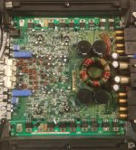
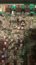
I am working on a Power 400a4 PC-2527C.
One power supply FET was shorted, replaced all 4 with IRF3205s and 47 ohm gate resistors. Also replaced 2- MMBTA56s (Q2 and Q3)in the power supply
RCA shield grounds broken. I have repaired them.
Crossover switch for Channels 3xx and 4xx broken, currently have switch removed and jumped for all pass.
Problem now, I am having trouble with setting the bias on the 400 series channel (left rear).
When I try to set the bias by monitoring voltage across the source resistor it starts at 0.060 mVdc and slowly climbs to 0.080 mVdc then suddenly, with the slightest movement jumps to ~3.4 mVdc. When I try and reduce the voltage by turning the pot back ccw , the voltage increases. If I turn it full ccw then cycle the remote it resets to 0.060 mVdc.
I have checked every 4xx resistor and they appear to be within tolerance, or at least match the other channels.
I have checked all transistors and diodes for shorts or open and they all seem fine in the 400 channel.
I have also cleaned the bias pot RV 404 with DeoxIT.
On the schematic 4xx is listed as right rear but in my amplifier it is tied to left rear output.
I am stumped. Where should I go from here?
Attachments
Last edited:
No Load I have +/- 30 Vdc on the rails and bottom and top clip at the same time.
With a 4 ohm dummy load the top clips before the bottom on ch4 and when the load is connected to any channel with a input signal the rail is pulled to +/- 10 Vdc.
With a 4 ohm dummy load the top clips before the bottom on ch4 and when the load is connected to any channel with a input signal the rail is pulled to +/- 10 Vdc.
It was either in the Rockford folder or one you attached to a previous thread. It shows PC-0952D.
Other than left and right channels being switched so far it seems to be very close. This amp had MTP75N05HD P.S. Fets and 10 ohm gate resistors and the diagram shows IRFZ40s with 10 ohm gate resistors. I replaced all power supply FETs with IRF3205s and 47 ohm gate resistors.
Other than left and right channels being switched so far it seems to be very close. This amp had MTP75N05HD P.S. Fets and 10 ohm gate resistors and the diagram shows IRFZ40s with 10 ohm gate resistors. I replaced all power supply FETs with IRF3205s and 47 ohm gate resistors.
There is a slight difference in that diagram and the one attached. In the attached diagram, look at D401 and D402. Do thos correspond to what you have in the amp or or the ones in the 0952 diagram (D402 and D403) what you have?
Attachments
Yes, D401, D402 and D403, are connected exactly like the schematic you attached in #8 above.
That is the same schematic I have. In the bottom right hand corner of sheet 4 the part number is listed vertically on the edge of the sheet as PC-0952-D.
That is the same schematic I have. In the bottom right hand corner of sheet 4 the part number is listed vertically on the edge of the sheet as PC-0952-D.
These diodes clamp the drive. I need to know if your amp uses 401/402 in these locations or the 402/403 diodes to we will use the right diagram.
I appologize, I don't guess I understand. The diodes in my amp are layed out exactly like the ones in the diagram you posted.
All 4 diodes are MMBD914s and they are oriented, with respect to anode/cathode, exactly like the diagram you posted in #8.
The transistors they connect to and they resistors they connect to are exactly like the diagram in post #8.
The component designations are exactly the same. The values of the resistors are exactly the same.
No, same behavior with regards to clipping.
With no load, top and bottom clip at the same time (at +/- 30 V), although the 'horizontal' part of the wave is not horizontal, it is angled both top and bottom.
With load the top is clipped before the bottom at +/- 13 V.
As soon as load is connected it is still pulling the rail voltage towards ground. The rail is +/- 13 V . When load removed rail goes back to +/- 30 V.
The rail voltage shouldn't drop unless your 12v supply voltage is dropping. Is your 12v supply voltage remaining relatively constant?
Does the rail voltage drop with the other channels?
Does this channel draw more current than the other channels when they are driven the same way?
Does the rail voltage drop with the other channels?
Does this channel draw more current than the other channels when they are driven the same way?
There must be something wrong with my power supply.
I tried two different amplifiers with two different signal input devices and with music the voltage is steady, but with a sinewave, 1kHz and 80 Hz, it pulls the power supply down to ~6 Volts. The analog meter on the power supply doesn't drop, but it is clear when checked with my dmm.
The power supply is a, Tenma 72-6180, 40 amp regulated ps.
The load is 4 ohm 100 watt non-inductive dummy load.
Okay, after going down that rabbit hole.
The power supply is fine, the voltage was dropping across the current limiting resistor in series with B+.
The amp pulls 8.5 amps with no current limiter in series with B+ and a 1 kHz signal into 1-channel all bias pots set full ccw.
It will not run with either the head lamp or 2 ohm dummy load in series with B+. Should I put a 10 amp inline fuse in series with B+ for further testing?
Should I re-solder D401?
Is ch4 now functioning like all other channels?
Yes, resolder the diode.
The 2 ohm resistor (and other limiters) is only for protection when testing at near idling.
If all channels appear to be OK at low power (near idling, up to a couple of amps, through the limiter) clamp everything down tightly to the heatsink and go with a fuse or watch the current meter on the 12v supply, ready to immediately remove power if there is a problem.
Ch 4 is functioning like all the other channels. Both top and bottom clip at the same time and all channels pull ~ 9 amps each when loaded.
Bias pot for channel 4 is still the same.
I can now hear a high pitched hum when any of the channels are loaded. The hum stops when I probe the speaker terminal with the scope probe. Now that I think of it I was grounding the scope on the rca shield. The speaker terminals without signals on them are grounded to the supply ground. I will move the scope reference and try that here in a little bit.
For virtually 100% of the time, the connection between the body of your scope and the 12v power supply ground is all you need. For more critical instances, you can use the probe's ground.
For the Rockford amp, grounding to the RCA shield was, in part, defeating the noise-cancelling circuit.
If you need the most accurate view of the output signal, ground the probe to the NON-bridging terminal for the channel being scoped.
For the Rockford amp, grounding to the RCA shield was, in part, defeating the noise-cancelling circuit.
If you need the most accurate view of the output signal, ground the probe to the NON-bridging terminal for the channel being scoped.
So I tried to reset all the bias's for each channel by watching the amp-meter on the power supply until I saw a slight rise in current then backed them up a tiny bit. Ch 1,2,3 read ~1.2 mV across the source resistors. Ch 4 reads 2.8 mV. the only thing that resets Ch4 is cycling the remote. Turning the pot only increases the voltage.
I will try heating the bias transistor Q407 while watching voltage across the source resistor tomorrow.
Anything else you can think of to try?
The humming is still there on all channels when a signal is put in. I was using a 1 kHz signal so when I switched the crossover to L.P. the hum went away. I have tried running the 2/4 position switch in different positions with a single input, a double input while jumping the rca shields and also 4 inputs by way of Y-adapters.
I guess one thing at a time but just thought I would mention the hum while it was on my mind.
- Home
- General Interest
- Car Audio
- Rockford Fosgate Power 400a4