Hello All,
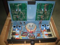
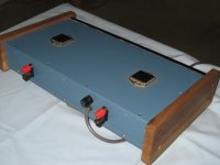
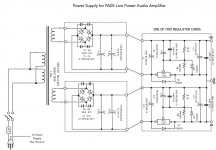
Back in the mid ‘90’s I had the opportunity to acquire, at a very modest cost, a few Apex PA05 power operational amplifiers, along with their evaluation kits. The amplifiers are rated for an internal dissipation of 250 watts, and a maximum supply of +/-100V. The evaluation kit contained a very nice heat sink with a thermal resistance of 0.68ºC/W, and a large PCB. I experimented with them as audio amplifiers (see attached pictures and schematics). I had no intention of pushing the power envelope, I was happy with 20-30 watts into 8 ohms, so I used +/-28V regulated power supplies. I used the amplifier for a couple of years as an office system listening mostly to FM. It sounded okay with speakers, but when I tried to use it as a headphone amplifier, the background hiss level was so bad I gave up and put the amp in the cupboard. At the time the only measurement equipment I had was an analog multimeter and an analog oscilloscope.
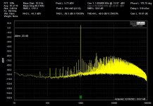
Recently I had the occasion to put the amp back in service for a few weeks while I worked on my current office system. While I had it out, I thought I would look at the distortion spectrum with the QA401 (see attachment), which looks pretty ugly to me. The data sheet specs the THD at 0.01% at 1KHz at 1W. Anyone care to offer suggestions on how to go about cleaning up all that distortion and noise? By the way, I am aware that the safety ground is incorrectly implemented, and if I can solve the distortion problem and put the device back into service, I will correct this error.
Cheers,
ceulrich
Back in the mid ‘90’s I had the opportunity to acquire, at a very modest cost, a few Apex PA05 power operational amplifiers, along with their evaluation kits. The amplifiers are rated for an internal dissipation of 250 watts, and a maximum supply of +/-100V. The evaluation kit contained a very nice heat sink with a thermal resistance of 0.68ºC/W, and a large PCB. I experimented with them as audio amplifiers (see attached pictures and schematics). I had no intention of pushing the power envelope, I was happy with 20-30 watts into 8 ohms, so I used +/-28V regulated power supplies. I used the amplifier for a couple of years as an office system listening mostly to FM. It sounded okay with speakers, but when I tried to use it as a headphone amplifier, the background hiss level was so bad I gave up and put the amp in the cupboard. At the time the only measurement equipment I had was an analog multimeter and an analog oscilloscope.
Recently I had the occasion to put the amp back in service for a few weeks while I worked on my current office system. While I had it out, I thought I would look at the distortion spectrum with the QA401 (see attachment), which looks pretty ugly to me. The data sheet specs the THD at 0.01% at 1KHz at 1W. Anyone care to offer suggestions on how to go about cleaning up all that distortion and noise? By the way, I am aware that the safety ground is incorrectly implemented, and if I can solve the distortion problem and put the device back into service, I will correct this error.
Cheers,
ceulrich
Attachments
-
 Low Power Audio Amplifier 1.jpeg502 KB · Views: 624
 -
 Low Power Audio Amplifier 5.jpeg286.6 KB · Views: 644
 -
 Low Power Audio Amp Schematic 4.jpg42 KB · Views: 699
 -
 PA05 Low Power Amp Power Supply 2.jpg59.3 KB · Views: 676
 -
 PA05 Low Power Amp - Left - Distortion at 1 W : 4 Ohms.jpg156.1 KB · Views: 593
1W @ 0.01% is base on max volume and reduced signal input.
BTW, your input ground to the amp board should connect from the star ground copper; not the potentiometer.
BTW, your input ground to the amp board should connect from the star ground copper; not the potentiometer.
If you turned off the 1K test tone, what would the output spectrum look like then?
If your 0db reference were 200 Watts instead of 1, how far below 0 would the noise be then?
What's the spectrum of the input signal? How much of the spectrum shown is the amp, how much is the input signal itself? I have two function generators; one has a much better spectrum for its sine wave function than the other. The better one isnt perfect either.
Weird I can't edit so add another post.
When doing measurement, the star ground must not short with earth ground.
Also, best if you can use a laptop running on battery to do the test.
The ground reference from your measuring device, connect to the star ground.
I don't recommend star ground connect to metal casing. It should reserve for earth ground in case of fault.
I'm not sure why you would want to use an amp chip that's designed for high power applications, like audio to 500 W, for a headphone amp. It's simply the wrong tool for the job, IMHO. The input noise spec for the PA05 is 10 uV, which is more than 1000 times higher than that for a low noise small signal op-amps. So 10 uV noise times the voltage gain of 10 = 100 uV or 0.1 mV of noise at the output (plus 10 X any source noise voltage) which I believe explains what you hear in the headphones. I do think the PA05 would make a great high power audio amp and I have seriously considered trying it. Recently I built two multi channel amps with its little brothers, the PA07 and PA12 and I'm quite pleased with the results.It sounded okay with speakers, but when I tried to use it as a headphone amplifier, the background hiss level was so bad

Well yes, you need pretty low noise circuitry for a headphone amp due to the fact your ears are close to the drivers.but when I tried to use it as a headphone amplifier, the background hiss level was so bad I gave up and put the amp in the cupboard
Typical headphones could be say 105dB/mW (135dB/W). If 15 ohms that's 135dB at about +12dBV, so 123dB at 1V,
so 5µVrms gives 17dB audio noise (definitely audible), and 5µVrms is 35nV/√Hz on the output, so if the gain is 3 that's 12nV/√Hz on
the input to give 17dB worth of hiss (although less A-weighted).
And configured as a power amp the PA5 will have a lot more gain than 3, so you might well have as much as 30 to 40dB of
noise used naively.
Typically you'd use a low-value resistive divider on the output of a power amp to drive a headphone, both for hearing
safety and to reduce the noise level.
?? Looks like a lot of zeros. 1 microVolt would be good for audio impedance and frequency. 10 times higher? (Which IS a lot).10 uV, which is more than 1000 times higher than that for a low noise small signal op-amps
You get 10 or 20 minutes to spot and fix your typos. 3 hours is past the edit timer.Weird I can't edit
Hello All,
Thanks for the great suggestions, I’ll work through them one by one.
PRR, the 60Hz signal is at -90-something dB, which I thought was not bad, and would not account for the hiss level. I did not hear any hum with either speakers or headphones.
jasonhanjk, please expand on your 1W @ 0.01% comment, I do not understand. The actual wiring is such that individual wires run from the input connector ground, and potentiometer ground to the star ground.
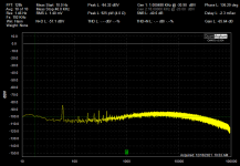
jjasniew, the noise level for the QA401 with shorted input is flat at -120dB across the full spectrum. Measured back in 2019, the THD for the QA401 1KHz signal, in a loop back measurement, was -89.2dB (0.00349%). Considering the PA05 amp itself, the attachment shows the distortion spectrum with a shorted input.
jasonhanjk, the measurements were taken using a laptop running on battery power. Yes, the safety ground is not implemented properly, I intend to rewire, such that the power ground goes directly to chassis, and a bridge style hum breaker goes between the chassis and star ground.
techtool, great point about the fundamental noise level of the chip. I built the amp intending it for use with speakers, and just as an after thought put in a connector for headphones. No design work was done.
Mark Tillostson, thanks for the analysis. Clearly documents the problem, and convinces me not to attempt to tweek it as a headphone amp.
Now that I have seen the distortion spectrum, I am wondering if I can clean it up enough to make a good audio amplifier? If I can get the THD at 1KHz and 1W down to around 0.05% I will be happy. My first thought was to reduce the gain and see what that gets me. Any advice on that idea?
Thanks for the great suggestions, I’ll work through them one by one.
PRR, the 60Hz signal is at -90-something dB, which I thought was not bad, and would not account for the hiss level. I did not hear any hum with either speakers or headphones.
jasonhanjk, please expand on your 1W @ 0.01% comment, I do not understand. The actual wiring is such that individual wires run from the input connector ground, and potentiometer ground to the star ground.
jjasniew, the noise level for the QA401 with shorted input is flat at -120dB across the full spectrum. Measured back in 2019, the THD for the QA401 1KHz signal, in a loop back measurement, was -89.2dB (0.00349%). Considering the PA05 amp itself, the attachment shows the distortion spectrum with a shorted input.
jasonhanjk, the measurements were taken using a laptop running on battery power. Yes, the safety ground is not implemented properly, I intend to rewire, such that the power ground goes directly to chassis, and a bridge style hum breaker goes between the chassis and star ground.
techtool, great point about the fundamental noise level of the chip. I built the amp intending it for use with speakers, and just as an after thought put in a connector for headphones. No design work was done.
Mark Tillostson, thanks for the analysis. Clearly documents the problem, and convinces me not to attempt to tweek it as a headphone amp.
Now that I have seen the distortion spectrum, I am wondering if I can clean it up enough to make a good audio amplifier? If I can get the THD at 1KHz and 1W down to around 0.05% I will be happy. My first thought was to reduce the gain and see what that gets me. Any advice on that idea?
Attachments
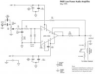
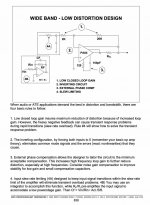
I'm baffled by the presence of C10 and R10. Sometimes such a network is employed to address instability (oscillation), but nothing I can spot in the Apex data sheet suggests it is necessary. The signal path gain is 10 (20 dB), but R10 introduces "noise gain" of 200 (46 dB), which might be responsible for the hiss you've noted. Its presence will also degrade distortion performance. I would suggest removing R10 and looking for noise (and perhaps THD) improvement. Be sure to use a dummy load and look for oscillation.
I'm bothered by the hum. The spectra looks suspiciously like intermodulation of hum and the test signal, as opposed to simple linear superposition. If you slightly vary the test frequency, do the "sidebands" move with the test signal, i.e. always offset 60 Hz? How does their amplitude vary with output load? e.g. no load vs. 8 ohm?
I'm bothered by the hum. The spectra looks suspiciously like intermodulation of hum and the test signal, as opposed to simple linear superposition. If you slightly vary the test frequency, do the "sidebands" move with the test signal, i.e. always offset 60 Hz? How does their amplitude vary with output load? e.g. no load vs. 8 ohm?
An interesting exercise is to apply noise to a given set of headphones through a variable voltage divider, with the variable resistor at the very bottom, so you can apply microvolts to millivolts. Turn it up until you can just barely hear it, then calculate or measure the amplitude. You'll be pretty shocked at how little noise is audible. Many receivers and power amps with a headphone jack divide it down and even then they all have more noise and hum than you'd like. What headphones really need is a purpose built headphone amp!
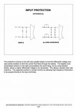
I had similar questions about R8, D3 and D4. According to the PA05 equivalent schematic on the data sheet, the inputs are internally protected by zener diodes, so D3 and D4 are not needed. Not really sure what R8 is for....... maybe someone could enlighten me.I'm baffled by the presence of C10 and R10
Hi techtool,
I had similar thoughts. Seems unnecessary for protection, problematic for distortion and added inside-the-loop phase shift.
I had similar thoughts. Seems unnecessary for protection, problematic for distortion and added inside-the-loop phase shift.
BSST,
I agree. Simple is better. BTW, I am in this thread because I have built two amps with Apex chips, which I like and use everyday. However, they don't seem to be very popular with others, maybe due to the cost. How about you?
I agree. Simple is better. BTW, I am in this thread because I have built two amps with Apex chips, which I like and use everyday. However, they don't seem to be very popular with others, maybe due to the cost. How about you?
I've looked at them occasionally over many years, but never used one. Probably due to their cost. They would be great for production test fixtures where the one-off cost wouldn't be an issue.
If I understand correctly, OP used an evaluation board. It probably has a multitude of options, many of which aren't appropriate in this application.
Best,
Steve
If I understand correctly, OP used an evaluation board. It probably has a multitude of options, many of which aren't appropriate in this application.
Best,
Steve
Hello All,
Thanks for the comments. I will put the amplifier back on the test bench tomorrow and try some of your suggestions.
Regarding the diodes and C10 and R10, I was following suggestions from an Apex Technical Seminar document (see attachments).
Cheers,
ceulrich
Thanks for the comments. I will put the amplifier back on the test bench tomorrow and try some of your suggestions.
Regarding the diodes and C10 and R10, I was following suggestions from an Apex Technical Seminar document (see attachments).
Cheers,
ceulrich
Attachments
Techtool, is that a small light bulb nestled between the transformers--- added viewing drama through the smokey top cover? Gorgeous work!
Ceulrich, thanks for the insightful attachments. I still suggest removing R10; that comports closely with Rule 1 in the Phase Comp note. Removing the diode networks introduces very little risk to the amps since the inputs are current-limited by the 10K input resistors. These two mods might improve the distortion spectrum. But hum is still finding its way into the signal path, so some mystery remains.
Please keep us posted and good luck!
Steve
Steve, thanks for the comments. That is an inline fuse holder between the transformers. Just trying to use up parts on hand and keep the rear panel from getting too busy.Techtool, is that a small light bulb nestled between the transformers--- added viewing drama through the smokey top cover? Gorgeous work!
David
I used to use Apex amps to drive piezoelectric devices. The HV parts worked great, and some of the audio parts really appealed to me, but it's no surprise they got no traction for DIY use, being at least a hundred bucks apiece. They were an excellent company to deal with.
- Home
- Amplifiers
- Chip Amps
- Apex PA05 Power Op Amp as an audio amp