Warning, I don’t know much about amp design. So, having said that….
Years ago I bought a cute SE 6bx7/6bl7 amp off of Ebay. It had a single 6j5 per side along with the output 6bl7. Also used some open frame output transformers. It was cheap but I liked it quite a bit. Gave it to a girlfriend so now no longer have it. I’ve read that the 6bl7 isn’t a good basis for an amp but I really enjoyed it and I’m thinking it would be cheap enough to replace. The power was sufficient for the speakers I have.
It was so cheap that I’m sure there weren’t any mosfet followers or anything. I assume that both triodes in the 6bl7 were paralleled for the output, would there be any advantage of using one of the triodes for something else? Do you think the 6j5 tubes were directly coupled to the output tubes? Is there a better way to design that? Thanks for any insight you can send me.
My guess is that it was a 6J5 gain stage direct-coupled to a parallel 6BX7 cathode follower. There was a popular audiophile preamp a number of years back, I forget the name, that used a 76 and a 6BX7 is a similar configuration.
That could be it, it certainly fits the description. With such a simple circuit, do you think there is much to improve?Maybe this one?
Electraprint 6BX7 SE
I just came across it by chance today when I saw a cheap offer for 6BX7s so cannot comment, but I saved it because I do like the elegance of simple circuits.That could be it, it certainly fits the description. With such a simple circuit, do you think there is much to improve?
Just found a push pull 6bx7 amp. It's being billed as a "30w push pull E-Linear 6bx7 amplifier." It is certainly much more complicated than the amp linked earlier but I don't understand how you could get anything approaching 30w of output power out of a single 6bx7. Even if we dismiss the power claim, does this amp look legit? Think it will perform better than the SE amp posted earlier?
You probably found this: https://doggenshozen.wordpress.com/2019/06/13/30w-push-pull-e-linear-6bx7-6bl7-amplifier/
The author seems to claim 15 Watt RMS from a single 6BX7 in push-pull. He also writes: "The output tubes sit at about 10.5 watts plate dissipation at idle between the two triodes.". I take that as meaning that the two plates in one 6BX7 are dissipating 10.5 Watt in total. This would be in line with the datasheets that state that the maximum dissipation of the two plates combined is 12 Watt.
There is no way you can get 15 Watt rms of audio power with this set-up. So I would not trust anything that is written in that 'article'.
Attached is a schematic of a class AB1 push-pull amplifier with 2 x 6BX7 (for one channel) giving an output power of 10 Watt RMS. Based on this you can expect about 5 Watt RMS from a single 6BX7 in class AB1 push-pull.
Links to the two articles mentioned in the attachements:
Radio Electronics February 1957 (see page 39)
Audio September 1959 (see page 40)
Last edited:
Glad to hear I was right in being skeptical. I am now intrigued by the possibility of a PP 6bx7 amp.
I converted an Eico ST70 to ppp 6BX7 - used one section of a 6DJ8 direct coupled to the 6SN7 inverter (retaining the original AX7 plate voltage), choke input for the output stage to get roughly 300vdc- no loop feedback - very nice and fun amp.
ST70 originally ran 7591 - the output transformers are every bit as good as those on HF87 and on a better chassis.
ST70 originally ran 7591 - the output transformers are every bit as good as those on HF87 and on a better chassis.
I ran a whole series of bench tests on single PP 6BX7s, 6SN7s, 6BL7s & 5998 about 3 yrs ago
under the header 'The Betty Crocker Special'. It was built in a cake tin, I wouldn't do that again.
Very difficult to work on.
All the tests were reported on DIY in a thread started by Lingwendil for his 'Flea Powered Amp'.
I had some concerns regards the OPT impedance selected on a PP 6SN7 so I dived in.
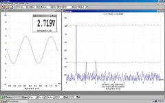
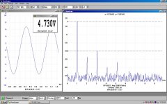
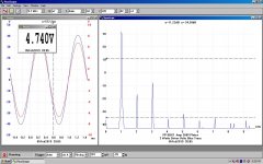
In Class A & without exceeding the dissipation limits a single PP 6BX7 is good for about 3W at clipping.
The 6SN7 about One Wat, the 6BL7 3W. The 5998 looks like a 6AS7, it was meant for regulated PS.
The PP 5998 managed a clean 10W.
under the header 'The Betty Crocker Special'. It was built in a cake tin, I wouldn't do that again.
Very difficult to work on.
All the tests were reported on DIY in a thread started by Lingwendil for his 'Flea Powered Amp'.
I had some concerns regards the OPT impedance selected on a PP 6SN7 so I dived in.
In Class A & without exceeding the dissipation limits a single PP 6BX7 is good for about 3W at clipping.
The 6SN7 about One Wat, the 6BL7 3W. The 5998 looks like a 6AS7, it was meant for regulated PS.
The PP 5998 managed a clean 10W.
Attachments
-
 PP 6BX7 Amp Schematic.JPG62.1 KB · Views: 232
 -
 PP 6BX7 260V PS One Watt.JPG111.2 KB · Views: 149
 -
 PP 6BX7 260V PS 3 Watts.JPG114.6 KB · Views: 88
 -
 PP 6BX7 260V PS 3 Watts Driver Blue Trace.JPG108.3 KB · Views: 108
 -
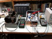 IMG_3994 Betty Crocker on the Bench.jpg266.1 KB · Views: 120
 -
 6SN7 Amp Betty Crocker Special.jpg361.4 KB · Views: 194
That sounds like fun. Although I imagine an ST70 with short tubes would look a little odd lol. What made you do that? Doesn't seem like an obvious mod to do.I converted an Eico ST70 to ppp 6BX7 - used one section of a 6DJ8 direct coupled to the 6SN7 inverter (retaining the original AX7 plate voltage), choke input for the output stage to get roughly 300vdc- no loop feedback - very nice and fun amp.
ST70 originally ran 7591 - the output transformers are every bit as good as those on HF87 and on a better chassis.
3w out of PP 6bx7. Not as big a power differential from parallel SE than I expected.I ran a whole series of bench tests on single PP 6BX7s, 6SN7s, 6BL7s & 5998 about 3 yrs ago
under the header 'The Betty Crocker Special'. It was built in a cake tin, I wouldn't do that again.
Very difficult to work on.
All the tests were reported on DIY in a thread started by Lingwendil for his 'Flea Powered Amp'.
I had some concerns regards the OPT impedance selected on a PP 6SN7 so I dived in.
In Class A & without exceeding the dissipation limits a single PP 6BX7 is good for about 3W at clipping.
The 6SN7 about One Wat, the 6BL7 3W. The 5998 looks like a 6AS7, it was meant for regulated PS.
The PP 5998 managed a clean 10W.
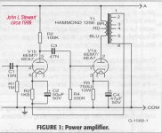
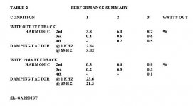
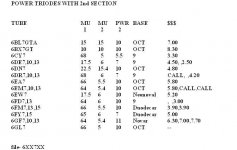
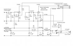
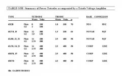
About 20 yrs ago I took a look at what it takes to build a low cost SET. The best tubes available at reasonable cost looked mostly like those used as vertical amplifiers in TV. Beyond that it narrowed down to the power triode best suited was something with a mu of ~5. Higher mu triodes in general need higher plate voltages while the lower mu triodes are more difficult to drive. The tube selected for the experiment was the 6EA7/6EM7, at that time low cost. Refer to the list of possible alternatives.3w out of PP 6bx7. Not as big a power differential from parallel SE than I expected.
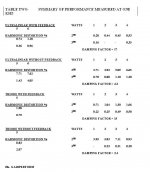
Rating the audio power available depends on how the limits of performance are set. Most would agree that a limit of 5% THD without NFB is passable. Using that as a guide, the tests shew that the 5% limit is reached rather soon. But more audio is available. And if one is OK with NFB the distortion is easily reduced in a simple FB pair. In this simple circuit any degree of NFB looks OK, there was no indication of instability.
I used a Hammond 125E universal OPT on this, meant for PP. But at 1000 Hz it was OK for the tests run.
The article covering this project was published in Glass Audio Volume 12, November 2000.
Attachments
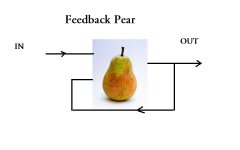
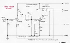
FB Pairs are possible in many flavors, So here is pentode-pentode.
This one has been running problem free since 1968, mostly in the workshop.
The other is from a presentation I did on FB Pairs in 2013.
Maybe it needs refreshing!
This one has been running problem free since 1968, mostly in the workshop.
The other is from a presentation I did on FB Pairs in 2013.
Maybe it needs refreshing!
Attachments
I would ditch the 6J6. That's an RF type that's specified for use as a mixer up to 600MHz. Mixing means nonlinear. Save the 6J6s for your RF projects. I would use a 6AU6 as a pseudotriode for the gain stage. (The 6J5 is also a good choice, but at the sacrifice of some gain. It's also an Octal type.) More linear, and the gain is roughly the same. I would also include some gNFB.That could be it, it certainly fits the description. With such a simple circuit, do you think there is much to improve?
For those still not completely bored with FB Pairs, here is yet another. This time triode- triode/UL
I was looking for more audio, several tetrode/pentode vertical tubes looked interesting. Refer to the list.
The 6LU8 looked like a way to go so using the earlier 6EM7 chassis I put this to the test.
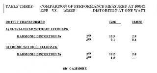
The experimental amp really needs an OPT built for SE, so a H1628A was wired in for a comparison.
This project was originally published in the Glass Audio Projects book of April 2002.
I was looking for more audio, several tetrode/pentode vertical tubes looked interesting. Refer to the list.
The 6LU8 looked like a way to go so using the earlier 6EM7 chassis I put this to the test.
The experimental amp really needs an OPT built for SE, so a H1628A was wired in for a comparison.
This project was originally published in the Glass Audio Projects book of April 2002.
Attachments
Miles P is absolutely correct, the 6J6 is meant for RF & does a great job there. But I am guilty of using a 6J6 for audio once,I would ditch the 6J6. That's an RF type that's specified for use as a mixer up to 600MHz. Mixing means nonlinear. Save the 6J6s for your RF projects. I would use a 6AU6 as a pseudotriode for the gain stage. (The 6J5 is also a good choice, but at the sacrifice of some gain. It's also an Octal type.) More linear, and the gain is roughly the same. I would also include some gNFB.
I'd built a simple PP 6AQ5 amp, 8W on a good day. It had built in Bass & Treble controls as well as a preamp for magnetic pickup.
But there wasn't enough gain in the 6C4 losser type tone circuit. The tube sockets were mounted on a phenolic board.
The easy way out was a Baxandal FB tone circuit using a 6J6, it fit the socket vacated by the 6C4,
In order to avoid PFB in that stage with its common cathode, bias was provided by a single SS diode.
The amp is inside a Hammond box with a handle, it went to many very loud house parties with vinyl, & loudspeaker.
Where large quantities of alcoholic beverages were consumed.
Think we had a very good time. And a few hangovers.
Attachments

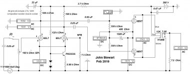
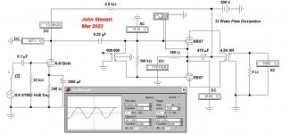
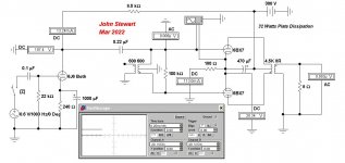
Here is the PP 6BX7 from Electra Print simulated. The 6J6 driver in the SE version is the same..Maybe this one?
Electraprint 6BX7 SE
The driver 6J6 fails badly driving the 8.5K plate load. For the lovers of distortion, this is the amplifier for you.
The single PP 6BX7 is burning in its socket with 32W plate dissipation.
That is still too much for even two separate 6BX7s, The circuit needs three,
As shewn, the circuit fails.
That last transmission was not supposed to go, I tried cancelling after an error was found in my simulation.
So here are the results corrected. In the simulation 10W is possible when the peak driving voltage drives the 6BX7 grids to clipping.
There is no tapped choke in EWB so here it is replaced by an OPT of 100H.
The 6BX7 plate dissipation is 32W, hard to believe Electra Print would do that. Perhaps two 6BX7s were used.
The SE vers uses the same 6J6 driver, that looks OK. Electra Print cct is in the PDF.
I'll try the SE vers later.
Attachments
- Home
- Amplifiers
- Tubes / Valves
- What is the probable configuration of a 6BX7 amp I used to own?