As mentioned in the main thread I set about taking the EL34 Baby Huey design and making a @pmillett inspired version of it: a single, large PCB for a stereo build with a few simplifications / tweaks. Basic parts, cheap coupling caps. Functional and easy to assemble.
I wanted to make the source files (not just the gerbers) available for all. This will allow others to take the base design (if it works well!) and alter for other valves / components fairly easily. It will also ease ordering should people want their own boards.
I've placed all the files needed here: https://github.com/tristancollins/HiFi-BabyHuey
KiCad sources
Gerbers
BoM
Schaeffer / Front Panel Express chassis files
The latest 'release' (v0.3) is here: https://github.com/tristancollins/HiFi-BabyHuey/archive/refs/tags/v0.3.zip
So in theory someone could order a PCB from PCBway, parts from Mouser, Toroidy etc, and a chassis from Schaeffer/FPE to get a pretty good looking and sounding stereo amp. [I used the same approach for my DCPP Engineer's Amp, so it'll look like the below picture.]

I'll detail my build in this thread. Another forum member is also building one, and the originator of the design (@gingertube) has a board too. So hopefully any issues will be found and I'll update the files accordingly.
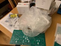
I started drawing a design in KiCad over 2 years ago, possibly 3 years ago! This morning I finally started assembly.
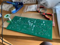
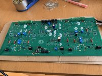
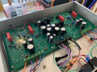
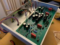
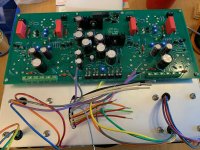
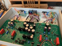
In 3 or 4 hours I was able to populate the PCB with all major components, starting with resistors and diodes, then moving to connectors, transistors and capacitors, in order of size. It was fairly simple. Photos attached.

Now I await the chassis to arrive from Germany... [update on chassis in post #16 ]
I wanted to make the source files (not just the gerbers) available for all. This will allow others to take the base design (if it works well!) and alter for other valves / components fairly easily. It will also ease ordering should people want their own boards.
I've placed all the files needed here: https://github.com/tristancollins/HiFi-BabyHuey
KiCad sources
Gerbers
BoM
Schaeffer / Front Panel Express chassis files
The latest 'release' (v0.3) is here: https://github.com/tristancollins/HiFi-BabyHuey/archive/refs/tags/v0.3.zip
So in theory someone could order a PCB from PCBway, parts from Mouser, Toroidy etc, and a chassis from Schaeffer/FPE to get a pretty good looking and sounding stereo amp. [I used the same approach for my DCPP Engineer's Amp, so it'll look like the below picture.]
I'll detail my build in this thread. Another forum member is also building one, and the originator of the design (@gingertube) has a board too. So hopefully any issues will be found and I'll update the files accordingly.
I started drawing a design in KiCad over 2 years ago, possibly 3 years ago! This morning I finally started assembly.
In 3 or 4 hours I was able to populate the PCB with all major components, starting with resistors and diodes, then moving to connectors, transistors and capacitors, in order of size. It was fairly simple. Photos attached.
Now I await the chassis to arrive from Germany... [update on chassis in post #16 ]
Attachments
Last edited:

Files don't open in KiCad for me - "Not an Eschema" but I'm totally new to this software, have a lot to learn. At least there's a pdf!
At first glance, I'd double up the feedback resistors (2x24K in series) - it's 700V peak - voltage margin is cheap! I'd prefer a 0V drop DC path to chassis, but would just jumper out the 0.1 uF cap. Also reduce the bias range (-1V at one end - really?) and eliminate the pot for the Power LED or add a series resistor. I was an engineer myself, know that adjustments that can cause damage will, sooner or later.
At first glance, I'd double up the feedback resistors (2x24K in series) - it's 700V peak - voltage margin is cheap! I'd prefer a 0V drop DC path to chassis, but would just jumper out the 0.1 uF cap. Also reduce the bias range (-1V at one end - really?) and eliminate the pot for the Power LED or add a series resistor. I was an engineer myself, know that adjustments that can cause damage will, sooner or later.
Thanks Tom - I should have said these are made in the latest version of KiCad - v6.02. Let me know if that doesn't work!Files don't open in KiCad for me - "Not an Eschema" but I'm totally new to this software, have a lot to learn. At least there's a pdf!
Thanks for these tips - interesting. The bias range is a bit extreme, agreed. And noted that allowing extreme ranges is dangerous. The LED adjustment in particular is a bit of a luxury I added as I hate having two indicators (one from preamp, one power amp) differing in brightness / luminosity. It took a few goes with my DCPP to get the right drop, hence using a trimpot.At first glance, I'd double up the feedback resistors (2x24K in series) - it's 700V peak - voltage margin is cheap! I'd prefer a 0V drop DC path to chassis, but would just jumper out the 0.1 uF cap. Also reduce the bias range (-1V at one end - really?) and eliminate the pot for the Power LED or add a series resistor. I was an engineer myself, know that adjustments that can cause damage will, sooner or later.
Adding a couple more details from yesterday's progress. I added thermal compound (a tiny amount) between Q201, Q202 and their heatsinks. The parts in the BoM are encapsulated in plastic so isolated from the heatsink. I used a couple of M3 screws and bolts
.
I also adjusted RV301/401 to read 680r - using the pads for R302/402 to take a reading. This brings the trim pot in to line with the schematic value - so in the ballpark of where it should be at first switch-on. Adjustments can be made from this point rather than at some (potentially random) point on the pot's travel.
Thanks for uploading all the files. I'm interested so I've downloaded them but I have to say that a single zip file would have been easier!
I had a lot of trouble opening the files in Kicad 6.0 initially but then realised I had to bring up the file on github and click download rather than simply right-clicking on the file and selecting "download link as...". What a pain!
My only comment so far is to avoid acute angles like this because they may trap acid during the PCB etching process.

I've just ordered some EL84 BH PCBs after my group-buy ones accumulated too many mods. It's so cheap to get your own made and I really enjoy the design process so I wouldn't order group-buy boards again.
I had a lot of trouble opening the files in Kicad 6.0 initially but then realised I had to bring up the file on github and click download rather than simply right-clicking on the file and selecting "download link as...". What a pain!
My only comment so far is to avoid acute angles like this because they may trap acid during the PCB etching process.
I've just ordered some EL84 BH PCBs after my group-buy ones accumulated too many mods. It's so cheap to get your own made and I really enjoy the design process so I wouldn't order group-buy boards again.
Last edited:
Thanks for uploading all the files. I'm interested so I've downloaded them but I have to say that a single zip file would have been easier!
You can download the whole repo a couple of ways - either clicking 'code' on the top right and there's an option to download a zip file, or in my 1st post there's a link to the v0.3 release as a zip which is a snapshot of the repo at that point.
Glad you got them to open though - that is reassuring.
I believe acid traps aren't really an issue any more at fab houses. I agree it would be nicer to have wider angles - I'll add that to tweaks in a future version.My only comment so far is to avoid acute angles like this because they may trap acid during the PCB etching process.
View attachment 1029911
I've just ordered some EL84 BH PCBs after my group-buy ones accumulated too many mods. It's so cheap to get your own made and I really enjoy the design process so I wouldn't order group-buy boards again.
Hi Tristan,
R323/423 have 22k/33k/39k 2W What is the optimal to use here? I've taken a middle of the road approach and gone for 33k. I should have read the BOM correctly.
Thanks
Earl
R323/423 have 22k/33k/39k 2W What is the optimal to use here? I've taken a middle of the road approach and gone for 33k. I should have read the BOM correctly.
Thanks
Earl
There’s a bit of a discussion about that here. Seems as though 18k - 33k is a range to try. I was going to tack in 22k first and give that a go.
One feature I was going to add was multiple pads for the R323/423 - to allow, e.g. two 39k in parallel to give 18k. Or even turrets, to allow more tweaking. But then I read in the main thread about stray capacitance or inductance being something to consider (related to the feedback loop?) and decided to leave that out.
One feature I was going to add was multiple pads for the R323/423 - to allow, e.g. two 39k in parallel to give 18k. Or even turrets, to allow more tweaking. But then I read in the main thread about stray capacitance or inductance being something to consider (related to the feedback loop?) and decided to leave that out.
Good job Tristan !
Juste a question, you use ground plane but without via stitching. Why ?
Do you know Kicad action plugin ?
Juste a question, you use ground plane but without via stitching. Why ?
Do you know Kicad action plugin ?
Thanks for the kind comments.
I spoke to a few way, way more experienced EEs than me who basically said stitching wasn't worth it at audio frequencies. And looking around at other manufactured hifi PCBs I don't see many using the approach. Also, I'd be nervous if the via count hit a limit with the cheap PCB fabs (not sure if there is one?) given the size of the board.
I had two options - a ground plane one side or a ground plane both sides. I couldn't get a good answer as to whether having a ground plane on both sides (potentially stitched together) was preferable. So I went with what Pete Millett does and have a single side ground plane.Juste a question, you use ground plane but without via stitching. Why ?
I spoke to a few way, way more experienced EEs than me who basically said stitching wasn't worth it at audio frequencies. And looking around at other manufactured hifi PCBs I don't see many using the approach. Also, I'd be nervous if the via count hit a limit with the cheap PCB fabs (not sure if there is one?) given the size of the board.
Yeah - I used one of the related plugins to be able to ease the layout generation - drawing one channel and being able to replicate it for the other. Saved quite a bit of time.Do you know Kicad action plugin ?
This thread started out as a topic of interest, but now it morphed into a treasure trove. Very useful conversation for someone (me) trying to get into KiCad. Thank you, gentlemen!
I'm thinking of getting ceramic valve bases from Cricklewood Electronics, or Watford Electronics. Any other recommendations?
I went with ones that look similar to the Cricklewood ones. That's a good point - I should include the data sheets / sources so that sockets used match the pin layout and chassis hole! I'll take pictures of the ones I have here - but 99% they are the same as Cricklewood but not gold or anything like that.
You're right. It's rare to see PCB with via between ground planes. I don't understand why. Vias give lowest impedance ground plane and better EMC performance on 2 layers PCB.I had two options - a ground plane one side or a ground plane both sides. I couldn't get a good answer as to whether having a ground plane on both sides (potentially stitched together) was preferable. So I went with what Pete Millett does and have a single side ground plane.
I spoke to a few way, way more experienced EEs than me who basically said stitching wasn't worth it at audio frequencies. And looking around at other manufactured hifi PCBs I don't see many using the approach. Also, I'd be nervous if the via count hit a limit with the cheap PCB fabs (not sure if there is one?) given the size of the board.
There is no via count with JLCPCB.
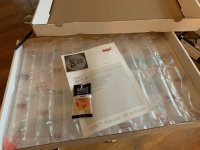
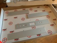
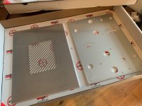
The chassis from Schaeffer arrived today.
Looking good apart from the holes for mounting the OT might be slightly too close together when I brought the two together for a quick test fit. A quick pass with a circular file should fix it if they are too tight.
I reckon I have all the parts needed to complete the build - just need a free day...
Attachments
So I managed to grab a few hours over the weekend to get this progressed. Attached are a few pics along the way.
Here’s where it’s at now:


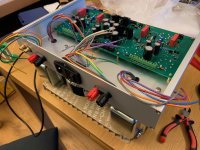
I started off afixing the transformers:

The output transformers fit, but it is very tight getting the bolts through.
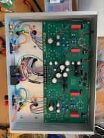
Then I got stuck in with the wiring:

If I have an issue with the power supply for heaters and driver I’ll be checking the contact within the terminal connectors: I had to remove the enamel coating from the power transformer wires with sandpaper and a scalpel. Not sure I got 100% of it removed.
Next steps are to put a fuse in the IEC entry, insert the valves and power it up! I’ll take a few days to get there and will do some checks first in case I’ve missed something obvious. And I’d need to think about where to set the bias trim pots to ensure nothing gets too toasty before I have time to adjust.
I’ll do the 1st power up in to dummy loads - and whilst I’m at it I’ll take some voltage readings through the circuit after adjusting for appropriate bias. I’ll also take Bode plots and an FFT / basic distortion reading (using a picoscope) and share them here.
Here’s where it’s at now:
I started off afixing the transformers:
The output transformers fit, but it is very tight getting the bolts through.
Then I got stuck in with the wiring:
If I have an issue with the power supply for heaters and driver I’ll be checking the contact within the terminal connectors: I had to remove the enamel coating from the power transformer wires with sandpaper and a scalpel. Not sure I got 100% of it removed.
Next steps are to put a fuse in the IEC entry, insert the valves and power it up! I’ll take a few days to get there and will do some checks first in case I’ve missed something obvious. And I’d need to think about where to set the bias trim pots to ensure nothing gets too toasty before I have time to adjust.
I’ll do the 1st power up in to dummy loads - and whilst I’m at it I’ll take some voltage readings through the circuit after adjusting for appropriate bias. I’ll also take Bode plots and an FFT / basic distortion reading (using a picoscope) and share them here.
Attachments

It is! I couldn't hold back. Just quickly this evening I powered it up.

Firstly with no valves installed - everything looked good. So I installed the valves:

And they lit up!
Voltages are higher than thought:
B+ is 400V
Bias is -127V
Driver is 16.5V
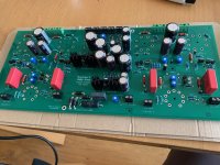
The CCS LEDs sure are bright - this pic doesn't do it justice.

I biased the EL34s to 40mA per side after things warmed up - it's a bit fiddly to get the balance so a bit of back and forth was needed between channels to get things balanced right. Then I adjusted the 12AX7 sides to match anode voltage (160V) - which was even more fiddly. There's about 0.9mA per side.
Here it is buttoned up:

And next to the DCPP:

I quickly hooked up the scope. I think there is quite a bit of adjustment to do to get distortion down (as judged from the FFT) and there is ringing on a 1kHz square wave at 1W output. I noticed a bit of a difference in output between channels too. Didn't have time to generate a Bode plot. There also might be a slight hum coming through, but I've yet to adjust the humdinger. So a few things on the to-do list.
I'm sat listening to it now. Immediate impression (compared to the DCPP) was slightly louder bass (I had to check if my preamp was set to have a slight bass boost!) but all good so far. Other than my ears playing tricks on channel imbalance perhaps.
Firstly with no valves installed - everything looked good. So I installed the valves:
And they lit up!
Voltages are higher than thought:
B+ is 400V
Bias is -127V
Driver is 16.5V
The CCS LEDs sure are bright - this pic doesn't do it justice.
I biased the EL34s to 40mA per side after things warmed up - it's a bit fiddly to get the balance so a bit of back and forth was needed between channels to get things balanced right. Then I adjusted the 12AX7 sides to match anode voltage (160V) - which was even more fiddly. There's about 0.9mA per side.
Here it is buttoned up:
And next to the DCPP:
I quickly hooked up the scope. I think there is quite a bit of adjustment to do to get distortion down (as judged from the FFT) and there is ringing on a 1kHz square wave at 1W output. I noticed a bit of a difference in output between channels too. Didn't have time to generate a Bode plot. There also might be a slight hum coming through, but I've yet to adjust the humdinger. So a few things on the to-do list.
I'm sat listening to it now. Immediate impression (compared to the DCPP) was slightly louder bass (I had to check if my preamp was set to have a slight bass boost!) but all good so far. Other than my ears playing tricks on channel imbalance perhaps.
- Home
- Amplifiers
- Tubes / Valves
- Stereo EL34 Baby Huey Build Log - an "Engineer's Baby Huey"