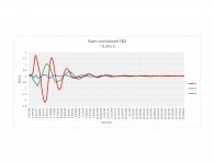
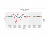
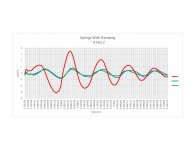
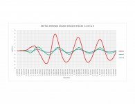
I’m playing around with a suspension for my new plinth and did some rough measurements of the two options that others might find interesting. In the plots below Z is up and down X& Y are horizontal. “springs” are a set of metal springs from a VPI HW19 “With Damping” means with the original VPI foam inserts in the springs. “Foam” is mixed cell polyurethane designed for building or machine foundation isolation. “Constrained” means that I built a solid wrap in the XY dimensions from plywood about 80% of the height of the foam blocks. I calculated the size of the foam blocks from the manufactures literature and should be getting a resonance close to what I get with the springs but I think the manufacturer’s data is based on wide thin sheets and the shape I am using (essentially a cube) is changing things a bit. One thing you can’t see in the roughly 1 second of data I posted for each is that the undamped springs rang for an incredibly long time, minutes in fact. The vpi foam inserts while they did raise resonance a bit cut the ringing time considerably.
Attachments

That foam must be very stiff to more than double the oscillation frequency - significantly stiffer than the spring itself in fact if I calculate right.
Do you know what natural frequency the arm+cartridge oscillates at? You probably should avoid that matching the suspension.
BTW that building insulation is probably closed-cell foam (to make it waterproof), whereas for damping an open-cell foam would be much less stiff and probably more lossy (which you want for damping).
Hello Mark,
My arm / cart resonance is about 11 Hz but I want the resonance of the suspension below 5.65 Hz to be compatible with the widest possible range of arm cart combo. The foam inserts for the spring are open cell and relatively coarse. The foam isolation material is very fine cell, I can’t see the cells with the naked eye on the cut edges. when I squeeze it underwater it will soak some up so maybe by “mixed cell” the manufacturer means a combination of closed and open? I should be able to adjust the size of the blocks to get in the 5 Hz range then the questions are how much does it creep under load and is it too well damped to attenuate the motor noise.
My arm / cart resonance is about 11 Hz but I want the resonance of the suspension below 5.65 Hz to be compatible with the widest possible range of arm cart combo. The foam inserts for the spring are open cell and relatively coarse. The foam isolation material is very fine cell, I can’t see the cells with the naked eye on the cut edges. when I squeeze it underwater it will soak some up so maybe by “mixed cell” the manufacturer means a combination of closed and open? I should be able to adjust the size of the blocks to get in the 5 Hz range then the questions are how much does it creep under load and is it too well damped to attenuate the motor noise.
The foam constrained case seem to have a resonance about 2.5 times higher in frequency. In a spring-mass system frequency goes with the square root of spring constant and reciprocal square root of the mass, suggesting that foam is stiffening the system by a factor of around 6. For the unconstrained case its about 3 times - this is not just damping, its dominating the effective spring constant too. Perhaps the springs aren't doing much in this case and you could just use foam blocks?
If the cell is too open it won't add much drag, if its too closed it will trap air at the oscillation timescale and act more like a spring - ideally you'd use a liquid for damping to avoid the pneumatic spring effect, but that can be messy. I suspect you won't get critical damping using air filled foam without a large shift in resonant frequency (but once you have critical damping that won't matter of course).
If the cell is too open it won't add much drag, if its too closed it will trap air at the oscillation timescale and act more like a spring - ideally you'd use a liquid for damping to avoid the pneumatic spring effect, but that can be messy. I suspect you won't get critical damping using air filled foam without a large shift in resonant frequency (but once you have critical damping that won't matter of course).
Maybe it is a silly idea, but early cars used friction damping.
In a turntable, a smooth piece of plastic or metal between two foam blocks with adjustable pressure until critical damping is achieved.
In a turntable, a smooth piece of plastic or metal between two foam blocks with adjustable pressure until critical damping is achieved.
The problem with solid, sliding friction is its stop-start in nature, causing noises. Viscous damping is what you want for quiet action.
I probably was not clear in the original post. The foam and foam constrained are using the isolation foam as the springs, no metal springs involved. I can reduce the resonance point by decreasing the size of the foam in the X or Y dimensions and should be able to tune below the 7 Hz I am getting now. The doubts I have about that working are basically creep and potential over damping.
I may be thinking about this the wrong way but I believe the amount of damping I can apply is related to the amount of noise transmission I can live with above Fs. The greater the damping the less attenuation as I understand it. My next tests will be mounting the suspension and motor to a board to see what noise transmission into the plinth is like vs the amount of damping applied.
I have an idea to try damping at the bearing housing which extends into the base rather than within the metal springs. Preferably by bending a foam ring if only because by altering the thickness or shape I have more tuning options.
I like the testing!
Many years ago (before I had CD's), I made a turntsble plinth out of several MDF slices. Suspension was by 3 squash balls placed underneath. Qualitatively, these have an ideal soft but very dead/damped characteristic. One was under the tone arm, and the others placed to level the plinth. They get a slight permanent flattening, so the plinth doesn't roll off. It worked well.
Many years ago (before I had CD's), I made a turntsble plinth out of several MDF slices. Suspension was by 3 squash balls placed underneath. Qualitatively, these have an ideal soft but very dead/damped characteristic. One was under the tone arm, and the others placed to level the plinth. They get a slight permanent flattening, so the plinth doesn't roll off. It worked well.
Nothing too scientific, I pushed down in the center of the platter until the suspension bottomed, paused a bit then let it go. I did that several times per test then clipped out the sections you see in the original post.Marth, how did you excite the system? Can you describe in detail. Thanks.
I should mention for anyone looking at the tests with the VPI springs as any indication of what a VPI HW19 will do, the plinth I am using is considerably heavier than the VPI stainless/acrylic plinth so tuning of the original HW19 will be higher.
John, sounds like it is worth trying. maybe I will order some squash balls.
Better than squash balls are Sorbothane hemispheres, also quite cheap. The hemisphere shape gives a large tolerance for mass range because the 'dome' squishes and increases contact area as mass increases. These hemispheres work so well that I doubt you will be able to measure the resonant frequency, yet they will give significantly greater isolation than your experiments above.
Sorbothane® Isolation Hemispheres
Sorbothane® Isolation Hemispheres

I'm willing to try them for sure. Do you have a size and duro you would recommend for 7.5 pound per isolator?
To be honest I buy cheap Sorbothane hemispheres from fleabay with no duro rating. I've got packets of 4 each of 30ø, 40ø and 50ø hemispheres so I can just select on test. They have an very wide functional weight range and any of the three sizes above would 'work'. I'd try ~40ø.
Pictured below is my 1972 Rega Planar 3 with Tangospinner feet (they have an o-ring in the bottom but are mostly decorative - still better than the Rega original) sitting on a slate sub-plinth with three 50mm hemispheres. I can hit the bench-top with a hammer while the stylus is on a non-rotating record and barely hear anything. I suspect this deck would play with a helicopter landing on the roof or through a minor earthquake, yet the plinth feels as solid as a rock.
(Ha, ha - I just noticed in the closeup photo that the decorative o-rings on the Tangospinner feet have perished and split. It happened to the finger-grip ones on the Tangospinner record weight as well so I bought replacements from an engineering company.)
Here are measurements I did some time ago.
TT is a Technics SP10 sitting on plywood with 4x cheap eBay springs under the ply. Output taken from the phono-pre into a Focusrite Solo.
Red trace is playing an unmodulated groove. Blue trace is a sweep from REW through the speakers with only the springs. Green trace a small piece of soft foam was inserted into each spring cage. No other changes were made apart from the foam.

These are pretty self explanatory. The 1kHz was for level reference.


TT is a Technics SP10 sitting on plywood with 4x cheap eBay springs under the ply. Output taken from the phono-pre into a Focusrite Solo.
Red trace is playing an unmodulated groove. Blue trace is a sweep from REW through the speakers with only the springs. Green trace a small piece of soft foam was inserted into each spring cage. No other changes were made apart from the foam.
These are pretty self explanatory. The 1kHz was for level reference.
Take a look at the Braun PS 500.
It is suspended on three springs, each spring is damped by an hydraulic shock absorber.
It is suspended on three springs, each spring is damped by an hydraulic shock absorber.
Isolation is the application of basic 'grade one' engineering mass / spring / damper implementation. I've been setting up turntables for nearly 50 years and it appears to me that not many turntable designers are graduate mechanical engineers.
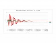
After a few failed experiments with foam springs and damping at the bearing housing I focused in on damping within the metal springs. I tried a few different materials ending up with blocks of foam cut from a magic eraser. This seemed to offer the best compromise between damping and resonant frequency. I’ve attached a zoomed in shot of the magic eraser damped metal springs and approximately 7 second clips of springs with no damping and springs with the magic eraser material for damping. I have some sorbothane hemispheres on order and I will see if I can get them to bounce.
One interesting thing I think I noticed in the multiple measurements I have taken is that the frequency of vibration in the different planes tends to converge. In most cases the frequency of vibrations in the x and y planes was higher than the in z plane, the z plane frequency went up as it tailed off ending 20-25% higher than where it started in one case. There seemed to be less disparity between frequencies with less damping in the springs but I think I would need greater control over the variables to be certain. You can see what I am talking about in the two bounce plots attached. The frequencies in the three planes line up pretty well in the undamped springs but are slightly off in the damped springs.
One interesting thing I think I noticed in the multiple measurements I have taken is that the frequency of vibration in the different planes tends to converge. In most cases the frequency of vibrations in the x and y planes was higher than the in z plane, the z plane frequency went up as it tailed off ending 20-25% higher than where it started in one case. There seemed to be less disparity between frequencies with less damping in the springs but I think I would need greater control over the variables to be certain. You can see what I am talking about in the two bounce plots attached. The frequencies in the three planes line up pretty well in the undamped springs but are slightly off in the damped springs.
Attachments

Hi. Have you considered a setup similar to Johnmath's but trying it on a pneumatic cycle tube instead of the Sorbothane hemispheres? You could then measure performance at different pressures. The sideways expansion of the tube would possibly act as something of a damper.
^ Hi, I have considered air suspension but I could not find bladders suitable for a multi-point suspension and wanted to get back to a more classic look so two-tier systems were out. I decided quite some time ago to explore the massive suspended route and incorporate a plinth with high internal damping. It would take tons of rework to switch to innertube suspension at this point and I am pretty happy with the tuning of the lightly damped metal springs.
I'll be very interested to see the results of your test with Sorbothane suspension, especially as you are measuring all 3 axis. The one time I tried an inner-tube suspension (years ago) I wasn't particular impressed. Any freedom of movement for the plinth is an ergonomic problem IMO (and can even lead to instability on a warped record) and inflating the tube enough to make the turntable stable eroded the isolation benefit compared to other methods. YMMV.
- Home
- Source & Line
- Analogue Source
- Some turntable suspension measurements