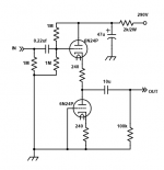
My apologies, by screen I meant the shield between the two triodes that is internally connected to the first triode's grid. My tests were for the device's suitability as a driver for a 6A3. They were cheap so I figured why not. I checked for gain and distortion with a CCS on the plate, and a 2 watt multiturn potentiometer bypassed with a 560uf capacitor to establish bias. The load was 100k capacitor coupled. Distortion measurements were taken using the FFT function on my oscilloscope. The resolution isn't great, but the tube would oscillate when hooked up to my soundcard. I could add a source follower to isolate the laptop from the load, but the harmonics were too high for my liking for that amount of work.
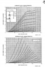
The curves I was looking for were from Tube Tester Files - 6N24P - 6H24P
Unfortunately, my results didn't match. For example at -5 volts 10ma my plate voltage was 175. . I don't have anything written down, but I did just get home and have a small bit of time before my weekend starts. I will try to get some concrete data to share.
Those almost flat lines at high negative bias are an indication of variable mu tubes . If you calculate the gain there should be very small .
That seems pretty linear, no?
I thought so too, but the FFT says otherwise. I am only swinging it 50Vpp. I don't see it being fit at double that. I may RC couple it to a source follower to try to keep it tame when connected to my sound card. Unfortunately I just haven't had a lot of time to play with these the last few days, and my birthday weekend has me booked.
Last edited:
Those almost flat lines at high negative bias are an indication of variable mu tubes . If you calculate the gain there should be very small .
I assume you are referring to the curves in the link I posted... The compression at the higher voltages and near cutoff are pretty typical for most triodes.
OK , if you say so ... then I don't think a curve tracer can "see" the true variable mu ... it is not static , you have to use 2 signals AC and DC .
Anyway it would have been nice to show both 6n23p / 6n24p characteristics with the same tracer , not to claim that are similar
Anyway it would have been nice to show both 6n23p / 6n24p characteristics with the same tracer , not to claim that are similar
Last edited:


Yes, I get that.
Am I right to think the remote cutoff pentode was developed after these cascode tubes?
Not so, variable pentodes predate variable triodes (acc. radiomuseum):
EF41 ---> 1948
EF51 ---> 1949
EF85 ---> 1951
EF89 ---> 1954
PCC89 ---> 1959
PCC189 ---> 1961
Reason: variable pentodes were only used in IF amplifier stages which required AGC,
whereas the triodes in cascode were exclusively used in VHF tuner frontends where regulation was not an issue.
Last edited:
Hopefully the image attached. I got up early and DC coupled a source follower. The best operating point I found at 60Vpp was at 10mA -4volts bias. At this point the 3rd harmonics dropped into the noise floor, but only at this point. Otherwise they were typically -15 dB below the 2nd. I tested all the way into to cutoff with current as low as 5mA. Mu was consistent throughout.
Attachments
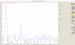
I would like to add that mu was measured at 30 with the new arrangement. I am guessing there was unseen oscillation that was robbing power in the previous tests.
This is the only one I have measured recently. I measured a triode strapped 6p15p a few years ago for a spud headphone amp. I ran into the screenshots of the measurements this morning, and the operating point I used measured (from memory) about -45 dB as well. But the operating point was selected for high current to overcome parasitic capacitance in the toroidal transformer I used for the output. Distortion was a secondary concern. 3rd harmonics where very much lower in the case of the 6p15p (again from memory). In Morgan Jones's 4th edition, there are some measurements for a number of tubes in the 6sn7 family. I took a gander this morning, and (from memory) the 2nd harmonics for the baseline 6sn7 at around 60Vpp (I think that was the level he measured at, don't quote me on that) were at -50dB. Not much difference there, however the 3rds with the 6sn7 and kin were 80 dB down.
With such a narrow window for keeping the high level of 3rds down on the 6n24p, I don't think it would make a good driver swinging 100 volts or more. As a cathode follower, or low level gain stage, I imagine it would perform just fine.
With such a narrow window for keeping the high level of 3rds down on the 6n24p, I don't think it would make a good driver swinging 100 volts or more. As a cathode follower, or low level gain stage, I imagine it would perform just fine.
Seeing how I may need a linestage for my current project, that looks like a perfect use for them. I appreciate that. I may use a negative voltage to avoid the input cap though.
"Variable Mu" is a misnomer. What we really want is a long toe of the low-Gm range, that Ik does not fall too low before Gm is very low.
This is more important in AM (and SSB). US AM radios soon had remote cutoff in IF, but also converter signal grid, and often the RF stage (if fitted) also. FM radio AGC can be much cruder. Cascode can be rigged so plate voltage shift varies cutoff.
"They" didn't invent remote cutoff, it was Stuart Ballantine.
- Home
- Amplifiers
- Tubes / Valves
- 6n24p / 6H24∏