Hey guys, I recently finished recapping a C370. All the caps on all boards have been replaced. No other components have been touched. All swaps were checked for correct values twice. All solder joints were measured for continuity with other joints on the same trace and also checked to ensure there is no continuity to neighboring traces.
I'm trying to get the unit fired up for the first time since the refresh and the following happens (dim bulb tester used):
- DBT switch is off
- Amplifier power button is in the "on" position
- DBT switch to "on"
- Amp power light turns on, DBT no light
~1.5 secs later
- Amp power light still on, something clicks in amp (sounds like relay), dbt flashes on and immediately shuts off along with another click from amp
The last event repeats about once every second.
I don't dare leave the DBT on for more than two cycles of this since I don't know what's going on.
Is this a result of all the caps being fresh and drawing too much current and setting off a protection circuit? If so, what's the solution - just let it click on and off until it settles down?
Or has something gone terribly wrong?
As I think about it, the above scenario is ultimately this:
The amp always starts out with the protection circuit engaged. Then it shuts off to let amp operate. In my case, it shuts off, senses a fault and, turns back on putting the amp into protection mode. Then it shuts off again and the cycle repeats.
I'm thinking of disconnecting the L + R output and preamp boards from the main board and trying again but I don't know if that will just throw the protection circuit into a different fault.
Did it work as it should have before you recapped the unit?
If so, hope you took pictures but go back and make sure all caps were put in the right way.
I assume you have tested all voltages from PSU to ensure they are correct?
My experience with NAD is that it will not work if you don’t have everything plugged in. So try and take a DC voltage measurement from the amp boards prior to the protection relay.
Report back and should be able to give you next steps.
Yup I took pics of everything. When putting in the new caps I checked that they match both board markings and the orientation of the old caps from the pics. I was incredibly thorough throughout the entire process so I'm a bit shocked it didn't just fire up normally.
Will do voltage measurements and report back. Thanks a bunch!
Will do voltage measurements and report back. Thanks a bunch!
Hello, I'm having trouble tracking down the culprit.
- I've re-checked that all caps are correctly installed.
- The protect circuit itself wasn't touched. I'd changed the smoked caps on it a couple of years ago and it's worked without issues.
I took measurements during the split second that protect allows the amp to turn on. I videotaped the DMMs and went back frame by frame to get readings during the moment that dim bulb tester is lit up.
Measurements:
- Both xformer secondaries are correct
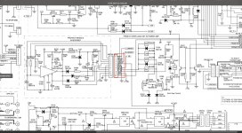
- At the power plugs between the main board and amp modules where I should be getting +- 64V I get ~ 6.5V on first "light up" and up to ~ 9.5V on second "light up".
- Output offset falls well within the +-30mv (between 4mv and 7mv) regardless of adjustment pot position
- Bias (taken at the two TP on each amp board) is 0mV regardless of adjustment pot position
So, given that the two amp boards are behaving exactly the same and neither is getting the proper +-64V, it's correct to assume the problem is on the main board correct (sanity check)?
If so, what should I be looking for (measurement wise)?
And last, should I trust service manual values at the protection circuit given that they show different values for L and R offset and some other discrepancies like "42V" on the 34V rail?
TIA!
- I've re-checked that all caps are correctly installed.
- The protect circuit itself wasn't touched. I'd changed the smoked caps on it a couple of years ago and it's worked without issues.
I took measurements during the split second that protect allows the amp to turn on. I videotaped the DMMs and went back frame by frame to get readings during the moment that dim bulb tester is lit up.
Measurements:
- Both xformer secondaries are correct
- At the power plugs between the main board and amp modules where I should be getting +- 64V I get ~ 6.5V on first "light up" and up to ~ 9.5V on second "light up".
- Output offset falls well within the +-30mv (between 4mv and 7mv) regardless of adjustment pot position
- Bias (taken at the two TP on each amp board) is 0mV regardless of adjustment pot position
So, given that the two amp boards are behaving exactly the same and neither is getting the proper +-64V, it's correct to assume the problem is on the main board correct (sanity check)?
If so, what should I be looking for (measurement wise)?
And last, should I trust service manual values at the protection circuit given that they show different values for L and R offset and some other discrepancies like "42V" on the 34V rail?
TIA!
Attachments
Curious, did you try the DBT before you recap'ed it? Maybe the protect ckt conflicts with the DBT, sensing a fault and powering down.
No didn't try that. Perhaps I'm not using the proper bulb? It's a 60 Watt - should I try a 100?
I'm a bit reticent to try without it but I guess if I need to I will.
I'm a bit reticent to try without it but I guess if I need to I will.
Try the 100W bulb, allow more power through to the amp. 6-9V on the rails is very low even for a 60W DBT, maybe something else is dragging down the power supply, will download service manual...
Try with 100W bulb first.
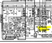
Consider disconnection power to the power amps, ie, disconnect connectors CB304(L) and CB404(R) and see if the voltages normalize, these CB's provide both power and GND, suggest use a jumper wire for the earth/GND connection just in case
Consider disconnection power to the power amps, ie, disconnect connectors CB304(L) and CB404(R) and see if the voltages normalize, these CB's provide both power and GND, suggest use a jumper wire for the earth/GND connection just in case
Consider disconnection power to the power amps, ie, disconnect connectors CB304(L) and CB404(R) and see if the voltages normalize
Yup, tried that as well. Makes no difference 🙁
suggest use a jumper wire for the earth/GND connection just in case
Do you mean while the power umbilicals are connected to the amp boards?
As you've already done, disconnect the connectors and see if the power supply normalizes, ie, check female connectors of CB. I noticed that the connector also included a GND connection, which would be broken when the CB was unplugged. I didn't do any anaylsis of consequences of breaking this GND path, thought easiest to just jumper the GND in unlikely event...
Did you try the 100W bulb? If voltages are still 7-9Vdc then time to check out the power supply...
Did you try the 100W bulb? If voltages are still 7-9Vdc then time to check out the power supply...
Attachments
Confirm all the supplies are present
It will not run up correctly if you start disconnecting connectors.
This amp has particularly delicate tracks, and also very close routing in places so it's very easy to short to an adjacent track when resoldering.
It will not run up correctly if you start disconnecting connectors.
This amp has particularly delicate tracks, and also very close routing in places so it's very easy to short to an adjacent track when resoldering.
On DBT +/-64V rails are very low. Is it the 60W DBT or fault in psu or fault in power amp stages. Connector disconnected to see if psu voltages normalize would suggest psu not at fault.
There's at least 6 rails you need to confirm:
+/-68 +/-64 +/-18 are all getting equally close to target.
I say again it won't power up correctly with connectors disconnected.
+/-68 +/-64 +/-18 are all getting equally close to target.
I say again it won't power up correctly with connectors disconnected.
Thanks guys. I'll check all the rails again (everything plugged in) just for a sanity check and then I'll go out and get a 100w bulb to see what happens.
I've taken some more measurements.
First, something I didn't mention before that may give a clue - the power light goes from orange (standby) to green (ok) and then back to orange (when protection circuit fires). At no point is the light red.
PSU -
Voltages on xformer secondaries are correct. Voltages from PSUs (after rectification and caps) are too low. I'm not sure what to make of this for two reasons:
1. The amp is actually on for just a split second at a time before protection shuts it off (I take measurements by videoing the meters in slow motion and scrolling frame by frame to get readings). Perhaps PSU doesn't have enough time to supply needed voltage?
2. There are 3 PSUs (68V rails, 64V rails, 34V rails) and they all behave the same. This leads me to believe it's not an issue with power but rather, as mentioned above, they just don't have time to provide needed voltage before protection shuts everything off.
Offset -
Left channel is within spec.
Right channel fluctuates somewhat violently and always overshoots the spec voltage. Playing with the pot, I can shift the voltage range but the fluctuations remain. Obviously a sign pointing to an issue with that board - I'll be reviewing it.
Bias-
Both channels show 0mV. Is this because the boards never get voltage from PSU?
Am I correct in the assumption that the PSU voltage issues and missing bias voltage are a result of the protection circuit shutting things off? Figure out why right channel offset is whacko and maybe everything else turns good?
Thanks so much 🙂
A fault (eg, near short) on one of the rails may drag down the other rails so they all look low.
Thanks. Ugh, I hope I'm not dealing with multiple faults - harder to track down. I'm really confused by all this honestly. Every cap replaced was checked and rechecked for polarity, capacitance and voltage multiple times before and after replacement. All solder joints were checked for conductivity with their trace and against conductivity with adjacent traces. Anyway...it is what is, eventually it will reveal itself.
I don't know what's wrong with your amp, insufficient information/symptoms for diagnosis... Could be fault in the power supply ("somewhere") or a fault on one of the rails (dragging the others down). My next step would be to isolate the power supply and see if it normalizes, if it doesn't "stand up" when unloaded then dig into the psu, otherwise identify the problematic voltage rail. Yes, I'm talking about unplugging connectors, see previously...
- Home
- Amplifiers
- Solid State
- NAD C370 help pls