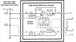
AN6558 seems unobtanium, but the good old NE5534A is likely somewhat quieter anyway, or a modern JFET opamp might be a good choice (for low current noise).
The RF suppression 100pF cap ideally is as early as possible in the signal path, certainly not after the electrolytic which could be large enough to radiate RF around the enclosure. Normally RF shunts go on the input connector directly for maximum effect.
R1 is unclear in its function, other than adding a little Johnson noise. Protection perhaps? I'd simply lose R3 and C1 as well, especially if a JFET opamp was used.
i second mark's comments. at least they did a little more than the reference design from the datasheet.
🙂
https://industrial.panasonic.com/content/data/SC/ds/ds4/AN6557_E_discon.pdf
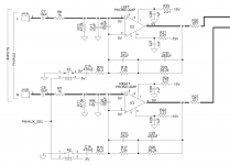
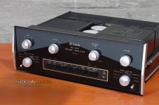
wiseoldtech, you might like to look at McIntosh phono sections from their preamps if you like this style. here's one from the C45 using a 5534A.
🙂
https://industrial.panasonic.com/content/data/SC/ds/ds4/AN6557_E_discon.pdf
wiseoldtech, you might like to look at McIntosh phono sections from their preamps if you like this style. here's one from the C45 using a 5534A.
Attachments
i second mark's comments. at least they did a little more than the reference design from the datasheet.
🙂
https://industrial.panasonic.com/content/data/SC/ds/ds4/AN6557_E_discon.pdf
wiseoldtech, you might like to look at McIntosh phono sections from their preamps if you like this style. here's one from the C45 using a 5534A.
The circuit that I showed in my previous post is taken from the Technics line of equipment.
It was used in many of their amps and receivers throughout the 70's and into the 90's.
I find it quite accurate as an RIAA preamp, with a smooth, rich, almost seductive response, definitely pleasant.
With accurate RIAA specs, it obviously made it through the decades with no major changes - why would Technics, a highly rated manufacturer insist on using it for so long of a time?
With 33 pf from outputs to negative inputs, and .1 uf ceramic +-15 local (<2.5 cm) you can use circuit in post 1 with $.38 ST33078. Much less hiss than NJM4558 but oscillates without the tweaks. Did it, still listening to it in a RA-88a disco mixer with Shure M97 Era IV cartridge.
Has anyone i made a PCB? I can design pcbs, but my experience is in digital / microcontrollers. Audio / analog layout is a different beast.
indianajo, i am looking for a mixer so I can have 2 phono interfaces to two sl1200, to connect them class d amps (tpa325x). In a perfect world I would like to have my dac connected also ( 2 V rms). Will be looking for one of the RA88. Can you share your mods?
indianajo, i am looking for a mixer so I can have 2 phono interfaces to two sl1200, to connect them class d amps (tpa325x). In a perfect world I would like to have my dac connected also ( 2 V rms). Will be looking for one of the RA88. Can you share your mods?
i'm not 100% sure but I think the service manuals for the McIntosh preamps has drawings of the pcbs, so you might be able to "freehand copy" the relevant bits and pieces using your CAD software of choice.
wiseoldtech might mention if the Technics manual where his schematic came from might have layout drawings also. i seem to remember they did for the old Technics products I owned or repaired over the years.
good luck!
wiseoldtech might mention if the Technics manual where his schematic came from might have layout drawings also. i seem to remember they did for the old Technics products I owned or repaired over the years.
good luck!
RA-88a will do all that. Comes in Herald Electronics also Olson Radio varieties. Detail of mod is Improving a "Disco mixer" to mid-fi performance - diyAudioindianajo, i am looking for a mixer so I can have 2 phono interfaces to two sl1200, to connect them class d amps (tpa325x). In a perfect world I would like to have my dac connected also ( 2 V rms). Will be looking for one of the RA88. Can you share your mods?
4558's out, 33078's in. Oscillated 1 mhz.
I drilled pcb & installed 33 pf feedback bypass cap on RIAA op amp, also .1 uf cap from +15 to -15. Bent leads over & soldered to trace. Oscillation gone.
Hummed, took out internal transformer & AC switch, powered now by external 18 vdc supply. Took out 330 ohm series resistors on DC rail. Took out headphone amp, repurposed DJ mike slide pot to a mono FM radio input to mixer. Has one line level stereo channel input already.
Has 2 outputs per side, low and high level.
wiseoldtech might mention if the Technics manual where his schematic came from might have layout drawings also. i seem to remember they did for the old Technics products I owned or repaired over the years.
good luck!
Unfortunately, I'm at a loss as to knowing where in my files of schematics a board layout would be.
Most all are mainboard located, and the one daughter board PDF I found is uselessly unclear foils.
Being a simple design, it should be an easy to layout, besides it's part of DIY on here, right?
Looking at the schematic that I originally posted, it's so simple to create and populate a PC or even a perforated hobby board with that circuit.
The layout can be identical to the schematic layout, perhaps with a few tiny mods.
A socket for the 8 pin IC, to play with different ones.
The layout can be identical to the schematic layout, perhaps with a few tiny mods.
A socket for the 8 pin IC, to play with different ones.
Frabor lives in the USA. Making a PCB legally in the USA involves a $450 deposit $30 a month rental 55 gal haz waste drum from Safety Klean or similar agency. Buying a PCB from our biggest foreign supplier involves software installation, A windows PC of same era as the software, a learning curve, exporting your credit card # outside the jurisdiction of the FBI. You can't legally make a PCB with tape, resist, a light box, a tray, and some simple chemicals anymore.
The used mixer I suggested in post 8 has 2 stereo RIAA circuits of that type in DIP format, 2 slide volume pots for the turntables and a left right fadeacross pot. It has a slide pot for a stereo line level input. It has a slide pot for a DJ mike input, which can be repurposed by gain change to mono line level input. It has a master volume out slide pot. It has a stereo op amp for mixing & RCA cable driving. It has 8 input and 4 output RCA jacks. It has a steel box to keep out the AM CB & police band radio waves. It has unfortunate levels of hiss & hum, but I beat those for about $20 in parts in my modification thread listed. I paid $15 for my RA-88a. I've posted to Mr Frabor, there is a similar looking device with a different brand name used on ebay today for $49. It should do what he wants, 2 RIAA in, 1 line level in, 2 stereo outputs. The pots and case & PCB alone are worth $49. Dip package circuits are so much easier to modify than the surface mount of a few years later technology. Your posted circuit post 1 is better, but not a lot. The RA-88a has a 1 megohm feedback circuit, which I haven't found to be a serious enough problem to change all the resistors & capacitors. Op amp change & oscillation kill got the hiss down to < the hiss of the gas pilot light in my music room. Hum kill was more difficult, time consuming, but not at all expensive. Wall transformer instead of internal AC transformer, then dual pi filter on DC input, plus RF killing chokes & capacitors on DC input.
The used mixer I suggested in post 8 has 2 stereo RIAA circuits of that type in DIP format, 2 slide volume pots for the turntables and a left right fadeacross pot. It has a slide pot for a stereo line level input. It has a slide pot for a DJ mike input, which can be repurposed by gain change to mono line level input. It has a master volume out slide pot. It has a stereo op amp for mixing & RCA cable driving. It has 8 input and 4 output RCA jacks. It has a steel box to keep out the AM CB & police band radio waves. It has unfortunate levels of hiss & hum, but I beat those for about $20 in parts in my modification thread listed. I paid $15 for my RA-88a. I've posted to Mr Frabor, there is a similar looking device with a different brand name used on ebay today for $49. It should do what he wants, 2 RIAA in, 1 line level in, 2 stereo outputs. The pots and case & PCB alone are worth $49. Dip package circuits are so much easier to modify than the surface mount of a few years later technology. Your posted circuit post 1 is better, but not a lot. The RA-88a has a 1 megohm feedback circuit, which I haven't found to be a serious enough problem to change all the resistors & capacitors. Op amp change & oscillation kill got the hiss down to < the hiss of the gas pilot light in my music room. Hum kill was more difficult, time consuming, but not at all expensive. Wall transformer instead of internal AC transformer, then dual pi filter on DC input, plus RF killing chokes & capacitors on DC input.
Last edited:
I don't know where indianajo's coming from with that enormous, rambling post #12, but when I started this thread, it was SIMPLY to offer a SIMPLE, easy to construct, QUITE satisfying, RIAA circuit.
Obvious choices regarding construction and type of IC chip are up to the person.
Obvious choices regarding construction and type of IC chip are up to the person.
Thank you Wise for your schematic and other ideas. they are much appreciated. I would also like to throw out this that I came across years back. It is an excellent sounding design with boards that can be ordered and a PS design that uses CLC in output and is very quiet!! I,m very impressed with this especially compared to quite a few others I have built.
Search DIY
CNC MM Phonostage PCBs, kits, modules and power supply
Search DIY
CNC MM Phonostage PCBs, kits, modules and power supply
Tks, I have been intrigued about designing a riaa amp for the longest time. I have designed multiple boards, but other than some simple signal conditioning, all low speed digital.
Definitely I look for sources of Macintosh. IN any case, seeing how the pcb was laid out makes the design process much easier as you get an initial idea of the optimal layout configuration.
Regarding the RA-88a, and after some rework drama this weekend, I am too clumsy with rework. A kit, or a drawing a pcb seems "easier" for me than rework.
...but, modding the RA-88a may be a lot of fun, and a chance to develop a new skill. I have not made my mind up. 🙂
idk about making large batches of pcb. I use eagle and https://dirtypcbs.com. Quality will not blow you away, the eagle board can be submitted directly and their express shipping rates are very reasonable.
idk about making large batches of pcb. I use eagle and https://dirtypcbs.com. Quality will not blow you away, the eagle board can be submitted directly and their express shipping rates are very reasonable.
wiseoldtech , sorry for kind of hijacking the post. After spending some days looking at receiver schematics I have to agree with you, the Technics is one of the best effort vs performance than can be built,and it can be easily made on a perf board. The specs of the McIntchosh c45 phono are supposed to be better (85dB s/n) but after looking at the circuits, very similar topology and implementation, more than likely the difference is mostly to the quality and implementation of the power supply. I have some kubota regulator and lm that I got from ali and some toroidals, I will give it a try.
wiseoldtech , sorry for kind of hijacking the post. After spending some days looking at receiver schematics I have to agree with you, the Technics is one of the best effort vs performance than can be built,and it can be easily made on a perf board. The specs of the McIntchosh c45 phono are supposed to be better (85dB s/n) but after looking at the circuits, very similar topology and implementation, more than likely the difference is mostly to the quality and implementation of the power supply. I have some kubota regulator and lm that I got from ali and some toroidals, I will give it a try.
I doubt you'll be sorry, honestly.
Like I said before, Technics used the same design for years in many of their amps and receivers - even the "high end' ones.
So they must have perfected it.
In my opinion, it's quite accurate and pleasent, and even with different cartridges it brings out the best in them.
Just make sure you house it in a metal enclosure, and a relatively simple linear +/-15v supply with proper filtering is all it needs.
Use a socket for the IC, to experiment with different ones.
Tks, I have been intrigued about designing a riaa amp for the longest time. I have designed multiple boards, but other than some simple signal conditioning, all low speed digital.
Definitely I look for sources of Macintosh. IN any case, seeing how the pcb was laid out makes the design process much easier as you get an initial idea of the optimal layout configuration.
Regarding the RA-88a, and after some rework drama this weekend, I am too clumsy with rework. A kit, or a drawing a pcb seems "easier" for me than rework.
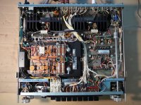
A few years ago (I was single at the time) I started a pre phono clone of MC Intosh MA6100.
I had listened to the original and found it excellent, hence my decision to clone it, but it was left unfinished for reasons that don't matter here.
I can upload photos and diagram again if there are interested.
I made the PCB with the "old" technique, a plate of copper-plated pertinax and iron perchloride.
Preamp MC Intosh MA-6100 (DIY)
Attachments
- Home
- Source & Line
- Analogue Source
- A Simple yet Respectable RIAA Preamp