Greetings all,
I had acquired the wave-guide in the title line and I rather like it with Beyma 380M. Thus, I was wondering, if it could became a good basis for Unity/MEH by extending it.
Design of the extension could be done using Marcel's ATH4 program. However, to use the program, I one would need to find the shape of the expansion curves of the current wave-guide along the x and y axes.
Would anyone have an idea how to do that with a reasonable degree of accuracy?
Kindest regards,
M
Last edited:
Why not make a tight fitting plug from some wine corks glued together and cut to shape, apply some release agent like vaseline or silicon spray to the waveguide and then fill it up with some sort of plaster? If you glue some small positional markers onto the waveguide on the center axis before, you can then take the finished mold and use a sharp saw blade to cut it in half on-axis. You should then have the contour you are looking for.
Last edited:
Because this does flare along its length, I imagine it would be a matter of finding a tangent part way out and building on that. It would remain that all you get from this is the mounting hardware and the throat expansion.
Greetings all,
I saw a tool to do it. It comprises a plurality of pins arranged side by side and held by friction bar across. It is pressed against the curved surface and the pits slide through the bar and establish the curve.
The problem is, i do not know, what it is called.
Kindest regards,
M
I saw a tool to do it. It comprises a plurality of pins arranged side by side and held by friction bar across. It is pressed against the curved surface and the pits slide through the bar and establish the curve.
The problem is, i do not know, what it is called.
Kindest regards,
M
Like this?
Extending the waveguide does not necessarily mean continuing from the end. This waveguide has already had termination. You might need to go back before that. To find the 90 degree tangents, insert the corner of a sheet of paper into the flare and see where it touches the sides.
Extending the waveguide does not necessarily mean continuing from the end. This waveguide has already had termination. You might need to go back before that. To find the 90 degree tangents, insert the corner of a sheet of paper into the flare and see where it touches the sides.
Attachments
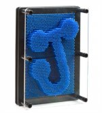
It is called a contour gauge, available to buy or I have seen them on Thingiverse for 3D printing.The problem is, i do not know, what it is called.
You can also measure the contour of horns with simple planar curves using a pseudo telescoping gauge. Use a marked dowel or ruler to establish the centerline of the horn (mouth to throat) and brace it both ends. Then create a T-gauge from thin dowels or bamboo skewers (pick straight ones 🙂 ) . Trim the T-gauge in order to move down the horn axis. This will give ZY and ZX measurements perpendicular to horn axial centerline.
Or you can get one that is already done. The manual measurements will have some noise, so I use a n-point B-spline to smooth the curve fit. The horn definitely has the OSWG profile from its radiation impedance curve.
Modular active 3 way - work in progress
Even better would be a 3D laser scan to generate a point cloud. Not sure if you can rent these but they are outside my budget for play things.
Are you only trying to improve the off axis performance? As already mentioned, the changes may need to occur earlier than the mouth.
Last edited:
Hi AllenB,
yes, that is it, just linear instead of 2D. I do understand that I will need to shorten the wave-guide to before the termination. But, it is not easy to see/feel where the termination starts, hence the desire to draw the curve.
Hi fluid,
thank you very much, I used the term "contour gauge" and found it.
Hi DonVK,
thank you for the link. Would it be possible to send me the profile that you measured?
What I would like to try is to extend the pattern control lower.
Kindest regards,
M
This should get you started. It was the easiest export from FreeCad. I would have preferred spreadsheet or text file. Ignore the green webbing, its residue from the b-spline curve fitting, I gave up trying to suppress it. 🙂
How will you check the result of your modifications.?
How will you check the result of your modifications.?
Attachments
The main benefit here would be getting something tangible you can bolt on to start the curve.. it just happens to dictate things for you when the throat has been laid out. I'd try to design something around it and fit it to a useable curve.it is not easy to see/feel where the termination starts, hence the desire to draw the curve.
Since it is rectangular the average curve will be somewhere between the middles and the corners.
The biggest issue will be the 40 degree part. This is small and will give you a long and tall mouth in that dimension if you continue. It might be possible to redesign that to a more manageable angle.
Hi DonVK,
thank you. See below for your question.
Hi AllenB,
the idea I had was to obtain the curves and use ATH4 to predict the response. If it agrees with the measurements I found on the web, or can myself, I will then delete parts of the curves and again use the ATH4 to design the rest of the horn.
Kindest regards,
M
I seems like you are trying to create an ATH4 profile that will use the PHRN-1014 as a base. Hopefully you will post some results of the experiment. I'm also wondering what else I could do with this horn.
Last edited:
Hi DonVK,
exactly. In my, perhaps wrong, conclusion form initial attempt with ATH4, the driver to horn interface has significant influence, so why not use something that works?
However, as luck (good/bad) would have it, I have acquired an axi-symmetric OS profiled wave-guide with a little rounding along the mouth, so to get more familiar with ATH4, I have been working on modeling that one to gain some experience. Not everyone is a computer wizard like you.
Kindest regards,
M
Hi AllenB,
Can you please tell me where you have found the information that the horizontal angle is 40 deg? I have used DonVK's *.pdf file, calculated the angles at the points therein and the horizontal angle (past the initial throat section) appears to be about 60 deg. I would like to assure that I have the correct expansion.
I have also cut a paper at several angles and the closes does appear to be 60 deg. I have read somewhere that the curve is an OS, so I will next calculate that expansion and compare the two curves. If the information that it is OS will prove to be correct, I will have a good indication both regarding the angle and the line where the two curves differ, so that I can extend the profile.
Then the ATH4 fun will start.
Hi DonVK,
would you have the curve without the red reference lines? If so, I could use the squares to read twice the number of points for a better accuracy. But, perhaps it is not necessary?
Kindest regards,
M
The biggest issue will be the 40 degree part. This is small and will give you a long and tall mouth in that dimension if you continue. It might be possible to redesign that to a more manageable angle.
Can you please tell me where you have found the information that the horizontal angle is 40 deg? I have used DonVK's *.pdf file, calculated the angles at the points therein and the horizontal angle (past the initial throat section) appears to be about 60 deg. I would like to assure that I have the correct expansion.
I have also cut a paper at several angles and the closes does appear to be 60 deg. I have read somewhere that the curve is an OS, so I will next calculate that expansion and compare the two curves. If the information that it is OS will prove to be correct, I will have a good indication both regarding the angle and the line where the two curves differ, so that I can extend the profile.
Then the ATH4 fun will start.
Hi DonVK,
would you have the curve without the red reference lines? If so, I could use the squares to read twice the number of points for a better accuracy. But, perhaps it is not necessary?
Kindest regards,
M
You usually can't be sure of the directivity by looking at the curves. This is where I got that information, but any changes you make can affect it - B-52 PHRN-1014 1" Horn 10" x 14" Bolt-On
Hi AllenB,
thank you for the link.
I am, at this point, not trying to ascertain directivity, but rather to establish the angles and shapes of the expansion curves in both directions, so that I can enter them into the ATH4.
Attached please find figures depicting vertical and horizontal curves. The blue has been read from DonVK's *.pdf's, the red is calculated from OS formula using 60 deg respective 90 deg coverage angle.
I definitely need a better approximation of the curves of the device.
Kindest regards,
M
Attachments
I think that goes to show something about why this waveguide is liked.
Did you use the CD throat angle in the OS calculations?
Did you use the CD throat angle in the OS calculations?
Hi AllenB,
I did use 0 deg. Do you think that if I recalculate for different angles, let us say in 5 deg increment, the results might change?
I think the next attempt will be to scale DonVK's drawings to 1:1, print them, cut the contour and ascertain how close it matches the device. If it works, I will then import it into CAD, scale it up and get more accurate measurements.
Kindest regards,
M
Last edited:
Yes, I suspect starting at a more realistic throat angle will bring the throats closer.. and then maybe a slightly smaller overall angle.
Hi AllenB,
than you for the pointer, I will try it.
Do you know is there is a spreadsheet, or will I have to write that math myself?
Kindest regards,
M
than you for the pointer, I will try it.
Do you know is there is a spreadsheet, or will I have to write that math myself?
Kindest regards,
M
- Home
- Loudspeakers
- Multi-Way
- Establishing B-52 PHRN-1014 conour?