Hi, I have a Yamaha A-S701 amplifier that recently has develop an annoying problem. If the power is off then the relay of the mains st-by module is starting to click on and then off after exactly 30 seconds.
That is happening sporadically, you cannot predict when and I cannot find why.
First I thought that there is some remote control in the home that is doing that but that is not the case.
Started to search the net and I found that this fault has appeared on many A-S series, 301, 501.
I've tried to change the typical "faulty" PP capacitors in the st-by module but it does the same.
Found a similar thread but it seems that no one solved the problem of the relay that seems that it has a mind of it's own :
Yamaha A-S501 relay issue | Audiokarma Home Audio Stereo Discussion Forums
Does anyone have the same issue or can someone help me isolate and find the problem ?
Thank you !
Tried several websites on this but like you --send it to a Yamaha dealer for power supply modification , even ones bought new had this problem .
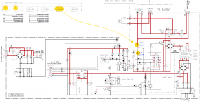
As its the stand-bye board and this mod seems to be kept "in house " then for a relay to operate it must have a voltage applied to it and if via a chip then the function "active " voltage is being built up .
I would temporarily connect voltmeters to various parts of the standby supply to narrow this down .
If its being provided from the main supply then trace that back.
This could be a slow progress but without the fault being provided on a plate then that's what I would do --work backwards to locate the source of power.
Thanks for the insight Duncan.
If even the new ones have this flaw wouldn't they have to "recall" the series or at least provide the "knowledge" to fix this ? Does Yamaha have an apple attitude ? 😛
I guess someone traced that to the +5S power rail and the VDD line :
"Sporadic Mechanical Click Noise while Standby SYMPTOM: Unit sporadically turns power relay on in the standby state. CAUSE: When receiving signal at remote control sensor during standby mode, the unit wakes up microprocessor from sleep mode and goes back to sleep mode again after keeping wake-up state for 30 seconds. In the event of state change from sleep mode, VDD line (5V) drops in a short moment just after rising rush current caused by +5S power supply startup. The voltage drop may cause unintended behavior that control line for power relay becomes active in the standby mode."
Btw, does your unit still have the jumper in the image or is it replaced with some capacitor or so ? That's on the right where the cpu board is located.
Thanks.
jumper - Image on Pasteboard
As I write this the relay is making more clicks than ever maybe knowing his clicking days are numbered..
Last edited:
Does the device have a transformer based PSU for stand by? Or is it a small SMPS?
They write that the 5V drops when the CPU starts but that would indicate a non optimal PSU. I think this is an interesting problem, probably a small cause with highly annoying effect..
They write that the 5V drops when the CPU starts but that would indicate a non optimal PSU. I think this is an interesting problem, probably a small cause with highly annoying effect..
Last edited:
It was pointed out in a couple of websites although a SKY remote activated the fault even without a remote it still occurred. That being the case its not just the remote that's causing activation and that some type of voltage pulse from the mains is generation a build up stored charge , this can be caused by electrical "leakage " due to bad filtering if left in standbye mode. I don't have one Muzyk_ant but I looked at a large picture of the standbye board with the two PP capacitors and the relay etc .
I had this problem on an Yamaha AS701 when using the phono section but sold it with the problem known to the buyer at the time. I never heard back from them.
Good luck on fixing it.
Good luck on fixing it.
Yeah, when it is gone problem solved isn't it? 😀 I searched and found this at a German website:
I think I would try out a 10 nf cap over R1 first. In German fora they write that C7 is likely the cause but many respond that this is not the case.
I think I would try out a 10 nf cap over R1 first. In German fora they write that C7 is likely the cause but many respond that this is not the case.
Attachments
Last edited:
Hey Jean-paul, I've already tried changing that capacitor but it still does the same bloody thing. I guess if that cap is faulty the unit doesn't start at all.
About that, I've spoken with a Yamaha representative and first of all they asked me if the issue occurs when anything plugged into the amp. As I told them that this occurs with the amp free of signal sources of speakers plugged in they asked me to speak with a yamaha service in my local area.I had this problem on an Yamaha AS701 when using the phono section but sold it with the problem known to the buyer at the time. I never heard back from them.
Good luck on fixing it.
One should measure if the base of the relay transistor Q2 is triggered by the CPU or by noise. I think the 10 nF is also nice to try out.
Next step: measure the 5V IC1 regulates and see if it indeed dips when the IR diode "sees" a signal and then triggers the CPU. I have some suspicion against IC1 as it is a completely unknown type and Yamaha telling the 5V dips.... Oscillation? A too high start up current of the CPU?
The paradox is often that the ones that own one can't/won't measure and the ones wanting to solve don't have one 🙂 The German fora have many contributions going in minute details about this issue but AFAIK they haven't found a solution.
Last edited:
I remember reading about Yamaha prologic receivers doing similar things. There was a debate about domestic appliances switching on and off automatically like fridge freezers, microwaves etc. These days we have additional things like WiFi operated temperature sensors to deal with. I'm currently having problems with a poor TV aerial signal cutting out when the central heating motorized valve operates. The tv glitches and freezes for a few seconds. The problems I was reading about before were tackled by having isolated/purified power supplies to the amp so that they didn't pick up any stray signals and interference.
I've tried putting on the first 10n cap that I found and it seems that for now it's quiet...stupid relay !
Will try to monitor that and see if it's getting on again and if not I will juxtapose a 10nf smd over the 100k resistor. Unfortunately I do not have a remote control for it to try if the st-by system wakes up from the remote.
So many many thanks till now if this seems to be the solution !!!
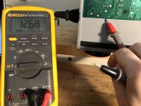
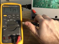
While trying to measure the 5V rail my left hand touched the laptop case which is aluminium and right hand the 701 case and it felt a little bit of a tingling... then I put the meter on AC and measured what shows in the pictures...
Only the positive lead shows from 5 to 12V and if i touch the negative it shows 70+ V ac on the amplifier case.
Could the culprit be in the amp not having an mains earth to it ?
Will try to monitor that and see if it's getting on again and if not I will juxtapose a 10nf smd over the 100k resistor. Unfortunately I do not have a remote control for it to try if the st-by system wakes up from the remote.
So many many thanks till now if this seems to be the solution !!!
While trying to measure the 5V rail my left hand touched the laptop case which is aluminium and right hand the 701 case and it felt a little bit of a tingling... then I put the meter on AC and measured what shows in the pictures...
Only the positive lead shows from 5 to 12V and if i touch the negative it shows 70+ V ac on the amplifier case.
Could the culprit be in the amp not having an mains earth to it ?
Attachments


Last edited:
Please consider that I am driving in the dark with no headlights. I have to rely on experience.
Any class I device should have its metal case connected to PE and a class II device isn't required to have that but most of these have plastic casings. Your leakage to chassis is logical and for that reason alone the chassis should be connected to PE. I build PSU's and this is a normal phenomenon and PE solves it straight away. Then the question comes up how to connect audio GND to PE 🙂
However I am not in the details of this device and why Yamaha had its Chinese subcontractor produce it like this (I am convinced only the label is "Yamaha"). If it would be my device I would certainly use a 3 prong IEC inlet without any delay as I am convinced PE to be a must with metal casings. That is if you like your life and that of your family members. If you are a dare devil you could use a 3 prong IEC inlet with built in mains filter with the right current ratings as well. Beware that examination has to be done whether/where audio GND is connected to chassis. When audio GND is connected to the chassis and no PE is used then it is built like many a DIY device: wrong 😉 It will then take effort to make it both safe and correct. This issue would have been found when certification institutions would still be testing devices that are imported.
I am glad the 10 nF cured the problem as I found out many seem to have the same issue with these but no one seems to have solved it. Therefor I would give it some time to see if it really is solved 100%.
Your remark on "stupid relay" should be "stupid omitted capacitor".
Last edited:
A new post to indicate Audio GND/PE details. Disclaimer: it is my personal system to avoid ground loops while having safety. Safety is non debatable IMHO. I have to deal with electrical safety a lot and I have seen many an accident or what happens when things don't work out too well so PE is also non debatable. No PE also means no filtering of mains filters the way they should/could. Only incompetent DIYers omit PE and/or connect Audio GND to chassis complaining PE causes hum...
We like to live and we want safety for everyone. However we of the mad DIY Audio crowd also don't like ground loops and hum. Dilemma.
So my way is this: analog power amplifier has Audio GND connected directly to PE. All source devices have PE connected directly to the casing but Audio GND is lifted with 100 Ohm (a cap in parallel may be required) to PE. In my personal opinion this solves ground loop issues and the cases are always safe to touch. There is no potential difference between devices Audio GND and PE so no static killing electronics, leakage current causing 70V AC on audio GND etc. Since Audio GND is connected to PE in the power amplifier also a short from L to Audio GND in a source device will trigger the breaker when devices are all connected. I hope you see what I did there.
I am very aware of regulations but also like stuff to perform. So, IF the Yamaha amp has audio GND directly connected to the casing you will (after careful examination) be able to use a 3 prong IEC inlet and then have to pay attention to your sources and their grounding scheme. Use washers, washer with teeth and sturdy bolt and nut and make sure to measure the PE wire to have ultra low resistance to casing. Have the yellow/green PE wire to have some over-length too.
Sure there will be posts indicating that the manufacturer knows best etc. but 70V AC on the casing tells otherwise. What will happen when L makes contact to the casing?
Last edited:
"What will happen when L makes contact to the casing?"
Do you want me to check that ? 🙂) just kiddn...
Well, If I measure now the potential from the case to my N wall plug that is 36VAC and from the case to the L that is 110VAC 🙁
Didn't want to make such a fuss about this problem but only to get it solved because I wanted to sell this amp for an upgrade and I cannot give this unit up knowing that is has this issue.
Could the culprit be that somehow the lack of a real ground and using the same GND for chassis and audio/microprocessor triggers the waking up of the cpu, respectively the 5V supply on the st-by relay ?
The fact is that I didn't understood why it triggers it so sporadically, I mean, you couldn't measure an exact time between it happens but only the on and off relay state which seems to be in all cases 30 sec.
Last edited:
Speculation and hearsay: I read that when IR triggers the CPU it is going back to sleep after 30 seconds. Seems to correlate.
Yes, it can be a train wreck of a grounding scheme not uncommon in OEM devices. It seems to be the case in this device but you can judge that. In any case we may conclude that we can not expect from so-called A brands what we used to expect from them many years ago. There is practically no mid class, there is very much ultra cheap, much cheap and less good. Prices sometimes in reverse order 😀
The question is what "real ground" exactly means though 🙂 I suggest to use the terms "Audio GND" for minus after the transformer as used by the audio circuits and "PE" (Protective Earth) for safety ground before the transformer so at mains voltage side.
Please let us know if you will be doing the PE thing and what the outcome is. I wouldn't sleep well selling a device with potential safety hazard, in fact I would like to recommend against it. Despite the brand name and good looks this device will fail regular electrical safety tests for sure. Leakage current to chassis may be low (enough) but a loose wire will cause electrocution. The tickling feeling is not well liked by many as well. Safety is substandard in this case, I say with some hesitation that adding PE can not harm anything (on the contrary...) but the encouragement to examine is not without reason.
Yes, it can be a train wreck of a grounding scheme not uncommon in OEM devices. It seems to be the case in this device but you can judge that. In any case we may conclude that we can not expect from so-called A brands what we used to expect from them many years ago. There is practically no mid class, there is very much ultra cheap, much cheap and less good. Prices sometimes in reverse order 😀
The question is what "real ground" exactly means though 🙂 I suggest to use the terms "Audio GND" for minus after the transformer as used by the audio circuits and "PE" (Protective Earth) for safety ground before the transformer so at mains voltage side.
Well, If I measure now the potential from the case to my N wall plug that is 36VAC and from the case to the L that is 110VAC 🙁
Please let us know if you will be doing the PE thing and what the outcome is. I wouldn't sleep well selling a device with potential safety hazard, in fact I would like to recommend against it. Despite the brand name and good looks this device will fail regular electrical safety tests for sure. Leakage current to chassis may be low (enough) but a loose wire will cause electrocution. The tickling feeling is not well liked by many as well. Safety is substandard in this case, I say with some hesitation that adding PE can not harm anything (on the contrary...) but the encouragement to examine is not without reason.
Last edited:

Thank you for the on the spot comments J. Paul.
I guess they omitted the PE because using that will get other issues like ground loops or something between this amp and another signal source, cd etc. that is also connected to the mains ?
I'm really thinking of what you are saying with the PE and everything. On the first hand I don't want to fiddle with it more than it should be... as you previously said : The Yamaha guys knew what they did... well... then the safety.. I will give it a try, as a partial mod and measure then again the case leaks.
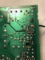
And here it is ! The smd cap (11nf 😛) on top of the R1-100k resistor. Funny that a non value part seems to always solve a $1000+ device... but in that case, the advice is 10X more valuable.
I guess they omitted the PE because using that will get other issues like ground loops or something between this amp and another signal source, cd etc. that is also connected to the mains ?
I'm really thinking of what you are saying with the PE and everything. On the first hand I don't want to fiddle with it more than it should be... as you previously said : The Yamaha guys knew what they did... well... then the safety.. I will give it a try, as a partial mod and measure then again the case leaks.
And here it is ! The smd cap (11nf 😛) on top of the R1-100k resistor. Funny that a non value part seems to always solve a $1000+ device... but in that case, the advice is 10X more valuable.
Attachments
Last edited:
Well... it still does the clicking 🙁.
The thing is that it does it much less often then before. Once a couple of hours compared to several times per hour.
One more thing I observed that powering up the amp has now a slight delay that is observable if you know how the amp started previously.
The thing is that it does it much less often then before. Once a couple of hours compared to several times per hour.
One more thing I observed that powering up the amp has now a slight delay that is observable if you know how the amp started previously.
#14 Use residual current device, RCD\ residual current operated circuit-breaker with integral overcurrent protection, RCBO.
OK, so we are in the right direction. That means there are signals that are picked up by the power relay driver.
The slight delay is logical and of no concern compared to the issue IMO. I would now use a 100 Ohm series resistor to make it even worse 🙂 And the issue less I hope. If you connect the casing to PE with a wire it would cancel the leakage current/voltage/potential differences that may have influence. This is the last time I will point at that as testing with a wire would be among the simplest of tests and the first test one should carry out when troubleshooting ...
Maybe you should do that first as it is 2 birds with 1 stone if you are lucky. Maybe the issue is then also gone. You can't break anything doing so but please measure the casing to Audio GND resistance. If there is no connection or just with a capacitor then the casing is an antenna for EMI/RF garbage instead of a shield. This would then be solved directly with PE. It would then be needed to made permanent with a 3 prong IEC inlet as suggested earlier on.
My idea is that internally generated EMI/RF or who knows what signals are picked up by the transistor. It could still very well be that the explanation of Yamaha also is valid. That would mean that there are at least 2 issues which would not surprise me.
These are more or less standard here but it is still required to have a metal casing connected to PE as risks add up.
The slight delay is logical and of no concern compared to the issue IMO. I would now use a 100 Ohm series resistor to make it even worse 🙂 And the issue less I hope. If you connect the casing to PE with a wire it would cancel the leakage current/voltage/potential differences that may have influence. This is the last time I will point at that as testing with a wire would be among the simplest of tests and the first test one should carry out when troubleshooting ...
Maybe you should do that first as it is 2 birds with 1 stone if you are lucky. Maybe the issue is then also gone. You can't break anything doing so but please measure the casing to Audio GND resistance. If there is no connection or just with a capacitor then the casing is an antenna for EMI/RF garbage instead of a shield. This would then be solved directly with PE. It would then be needed to made permanent with a 3 prong IEC inlet as suggested earlier on.
My idea is that internally generated EMI/RF or who knows what signals are picked up by the transistor. It could still very well be that the explanation of Yamaha also is valid. That would mean that there are at least 2 issues which would not surprise me.
#14 Use residual current device, RCD\ residual current operated circuit-breaker with integral overcurrent protection, RCBO.
These are more or less standard here but it is still required to have a metal casing connected to PE as risks add up.
Last edited:
- Home
- Amplifiers
- Solid State
- Yamaha A-S701 st-by random relay ticking problem